Method and device for bone stabilization using a threaded compression wire

a technology of compression wire and bone stabilization, which is applied in the field of bone stabilization using threaded compression wire, can solve the problems of limited use of threaded compression wire, and achieve the effect of facilitating purchas

Active Publication Date: 2005-02-24
ORTHOHELIX SURGICAL DESIGNS
View PDF17 Cites 11 Cited by
  • Summary
  • Abstract
  • Description
  • Claims
  • Application Information

AI Technical Summary

Benefits of technology

[0005] The present invention is intended to integrate some of the noted principles in a novel way. The concept is to use a partially threaded wire that has a sharp trocar point on an opposing end which is fixed in a bone in ante grade or retrograde fashion in order to attach two or more bone segments. The threaded end is kept in the distal or far bone segment to anchor that segment and to enable the compression between the segments. The wire is inserted through both bone segments and put into compression in order to adjoin the segments under a measured tension. The tension is maintained by a button which abuts a bone segment holding the non-threaded portio

Problems solved by technology

Plates tend to be rigid and their uses are generally limited

Method used


Image

  • Method and device for bone stabilization using a threaded compression wire
  • Method and device for bone stabilization using a threaded compression wire
  • Method and device for bone stabilization using a threaded compression wire

Examples


Embodiment Construction

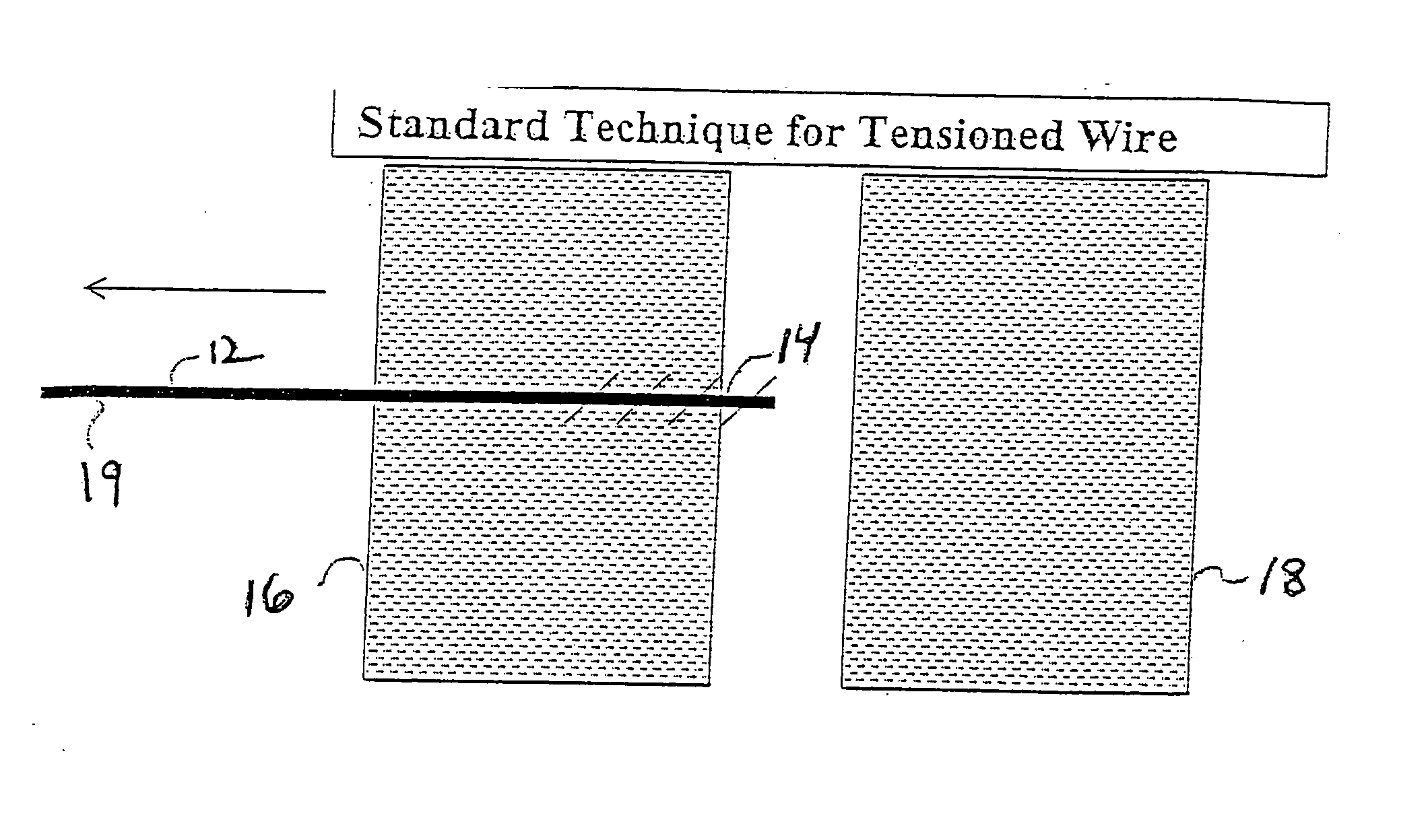
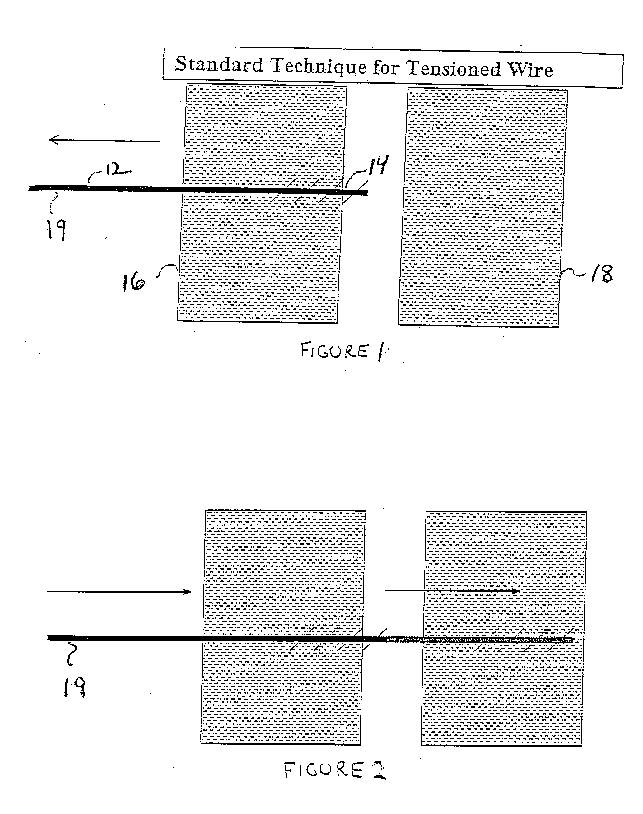
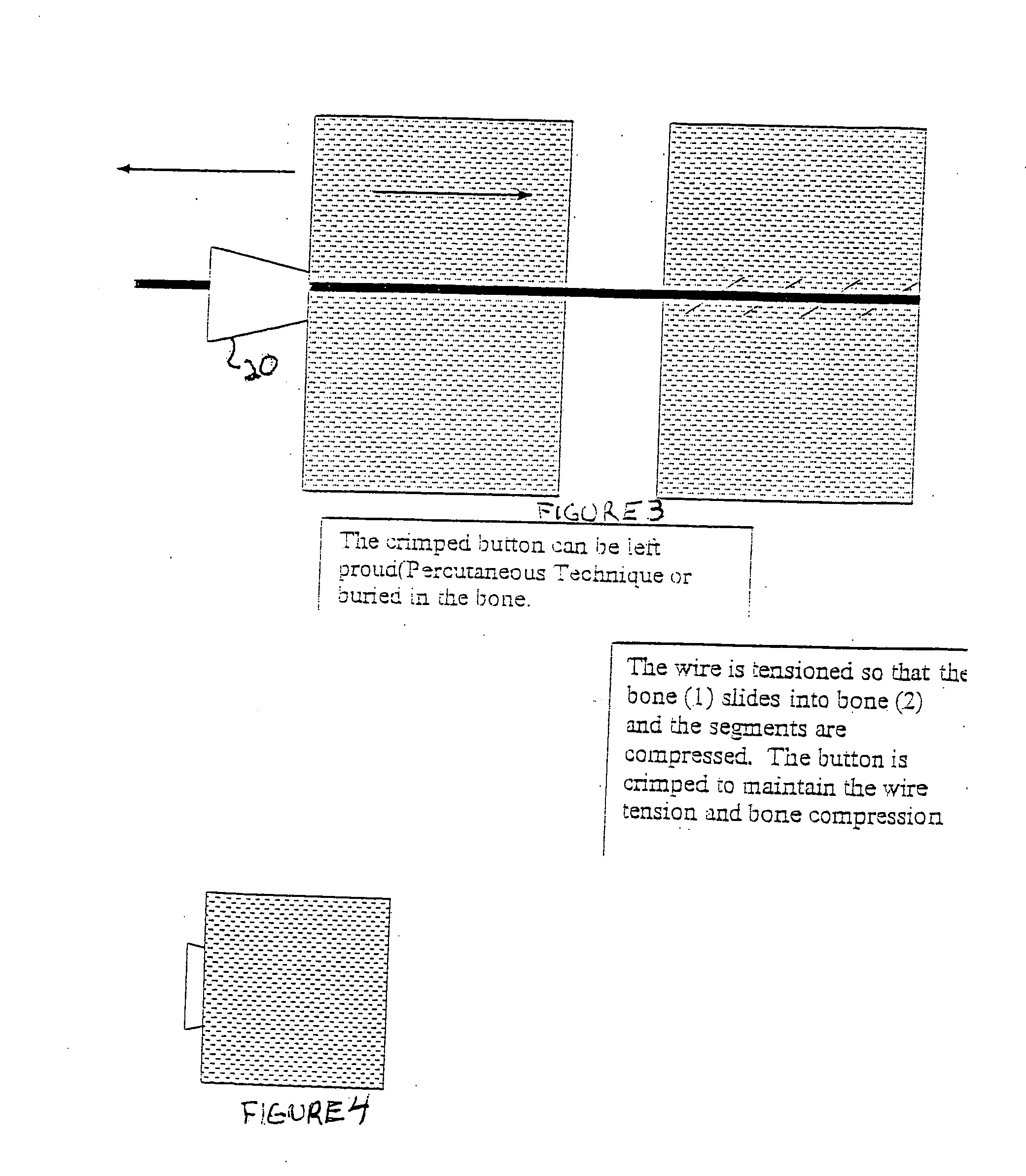
[0020]FIGS. 1-4 illustrate a standard technique in accordance with the present invention in which a wire 12 having a threaded end portion 14 is inserted through a first bone segment 16 into a far bone segment 18 where it is screwed in to anchor the second bone segment. A cannulated instrument is used which allows the wire to be implanted through the first bone segment 16 into the second bone segment 18. An end portion 19 of the wire is left protruding above the surface of the first bone segment 16 to allow access to the wire 12. A button 20 includes a hole that receives the end portion 19 of the wire 12. The button further includes means to crimp the wire into a measured tension in the button. The button is configured so that it applies pressure against the abutting bone surface of the first bone segment 16. A tension gauge can be used in order to assure that the wire is under the proper tension.

[0021] In the second embodiment which is illustrated in FIGS. 5 and 6, the external end...


PUM


Abstract

A compression wire is partially threaded and has a trocar insertion point for insertion into a bone segment to be stabilized with respect to a second bone segment. A button mates with the wire and is crimped into position on the wire to cause compression and stabilization between the bone segments. A cannulated instrument is used to grasp and apply tension to the wire at a given torque, and further to crimp the button to maintain tension on the wire in a location suitable for later removal. In a second embodiment for osteoporotic bone the wire further includes an internally threaded screw or helix which is implanted into the bone segment to mate with the threads of the wire. The invention further relates to the method of bone stabilization where the threaded wire is implanted into the distil end of a bone segment in ante grade or retro grade and also in a sub-cutaneous or percutaneous fashion and extending through an adjacent bone segment. An end of the wire protrudes from the second bone segment and end receives a button slid onto the wire and crimped into the desired tension. The end of the wire assembly may be left proud for later removal, or countersunk in the bone so as not to protrude.

Description

[0001] THIS PATENT APPLICATION IS BASED UPON U.S. PROVISIONAL APPLICATION SER. NO. 60 / 465,187 FILED Apr. 24, 2003[0002] The present invention relates to a compression wire for use in bone fixation where the wire is partially threaded and has a trocar insertion point. A button mates with the wire and can be crimped into position to cause compression. A cannulated instrument is used to grasp and apply tension to the wire at a given torque, and further to crimp the button to maintain tension on the wire in a location suitable for later removal. In a second embodiment for osteoporotic bone the wire further includes an internally threaded screw or helix implant which mates with the threads of the wire. The invention further relates to the method of fixation in which the threaded wire is implanted into the distil end of a bone segment in ante grade or retro grade fashion, the protruding end subsequently receives a button slid onto the wire so that it abuts near the bone segment. The end o...

Claims


Application Information

Patent Timeline
IPC IPC(8): A61B17/68A61B17/84A61B17/86A61B17/88
CPCA61B17/68A61B17/685A61B17/8869A61B17/8665A61B17/8863A61B17/848
Inventor KAY, DAVID B.
Owner ORTHOHELIX SURGICAL DESIGNS
Why Eureka
Try Eureka