Plate evaporator

a technology of evaporator and plate, which is applied in the direction of laminated elements, lighting and heating apparatus, and separation processes, etc., can solve the problems of increased manufacturing cost of high temperature brazing, reduced strength, and difficult control, and achieves cost saving and high yield rate

Inactive Publication Date: 2005-03-03
INVENTEC CORP
View PDF3 Cites 4 Cited by
  • Summary
  • Abstract
  • Description
  • Claims
  • Application Information

AI Technical Summary

Benefits of technology

[0012] The object of the invention is to provide a plate evaporator that has a high yield rate of manufacturing.
[0014] Also, no graphite fixture is required so as to save cost, and a high yield rate is achieved.

Problems solved by technology

In conclusion, the conventional manufacturing process for plate evaporator has the following drawbacks: 1) The quality of the capillary structure 14 due to oxidation in welding process is hard to be controlled; 2) The physical characteristics of the plate evaporator are varied, and strength is decreased, due to the high temperature of brazing; 3) The manufacturing cost is increased for the high temperature brazing; 4) Some graphite fixtures are required for supporting the components during brazing.
The fixtures are easy to be damaged because force is applied on.

Method used


Image

  • Plate evaporator
  • Plate evaporator

Examples


first embodiment

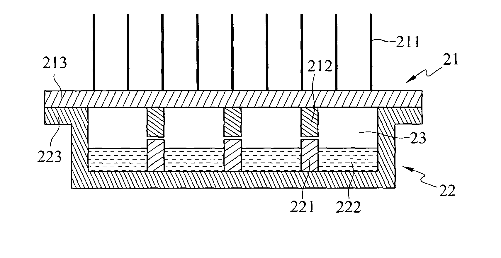
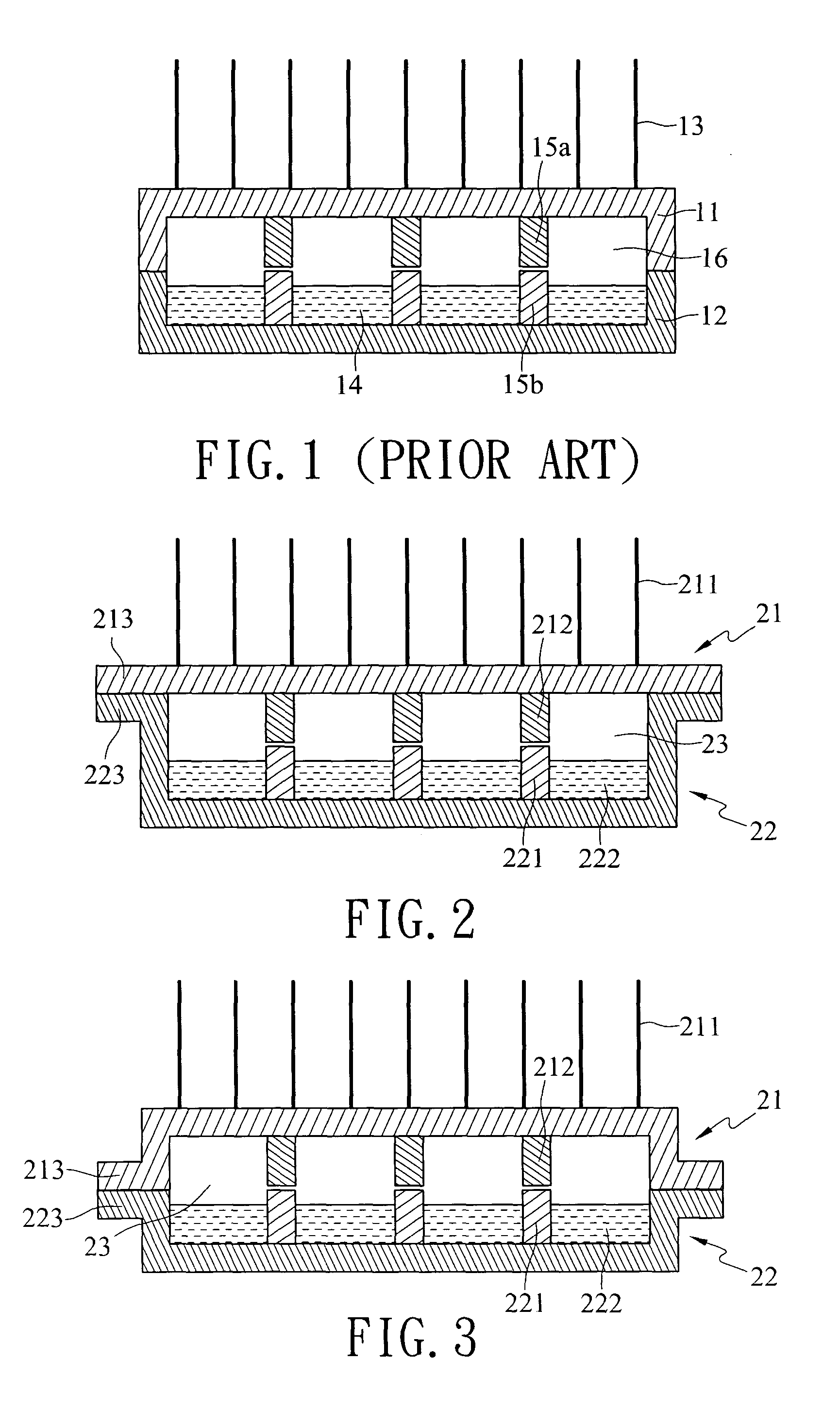
[0019] As shown in FIG. 2, a plate evaporator as the invention includes a first thermal conductive element 21 as a condenser, and a second thermal conductive element 22 as an evaporator. The first thermal conductive element is a plate element having outer surface tin-soldered with a plurality of heat-dissipation fins 211, and inner surface formed with first reinforced blocks 212. The reinforced blocks 212 are used to prevent the first thermal conductive element 21 from deformation during manufacturing process. The rim of the first thermal conductive element 21 is formed with a first joining portion 213.

[0020] The second thermal conductive element 22 is like a cap. Second reinforced blocks 221 are formed on inner surface of the second thermal conductive element 22 and correspondent to the first reinforced blocks 212 for preventing the second thermal conductive element 22 from deformation during manufacturing process. Capillary structure 222 is also formed on the inner surface. The ri...

second embodiment

[0022] As shown in FIG. 3, a plate evaporator as the invention includes a first thermal conductive element 21 as a condenser, and a second thermal conductive element 22 as an evaporator. The first thermal conductive element is like a cap having outer surface tin-soldered with a plurality of heat-dissipation fins 211, and inner surface formed with first reinforced blocks 212. The reinforced blocks 212 are used to prevent the first thermal conductive element 21 from deformation during manufacturing process. The rim of the first thermal conductive element 21 is formed with a first joining portion 213.

[0023] The second thermal conductive element 22 is like a cap. Second reinforced blocks 221 are formed on inner surface of the second thermal conductive element 22 and correspondent to the first reinforced blocks 212 for preventing the second thermal conductive element 22 from deformation during manufacturing process. Capillary structure 222 is also formed on the inner surface. The rim of ...


PUM

PropertyMeasurementUnit
thermal conductiveaaaaaaaaaa
yield rateaaaaaaaaaa
strengthaaaaaaaaaa

Abstract

A plate evaporator includes a first thermal conductive element and a second thermal conducive element. The rim of the first thermal conductive element is formed with a first joining portion. The second thermal conductive element is like a cap having a second joining portion at the rim and correspondent to the first joining portion of the first thermal conductive element. Therefore, upon assembling the two thermal conductive elements, the first and second joining portions are engaged. When brazing, only the joining portions are at high temperature. The temperature rise does not apply to the whole thermal conductive elements and does not influence the strength of the structure.

Description

BACKGROUND OF THE INVENTION [0001] 1. Field of the Invention [0002] The invention generally relates to a plate evaporator applicable to heat dissipation, and in particular relates to a plate evaporator with higher manufacturing yield rate. [0003] 2. Related Art [0004] Plate heat dissipaters similar to the one illustrated in FIG. 1 are developed. The plate heat dissipater, or evaporator, mainly includes a braze condenser 11 and an evaporator 12 formed into two caps. The outer surface of the condenser 11 is formed with fins 13 for heat dissipation. The inner surface of the condenser 11 is formed with some reinforced portions 15a in order to prevent from deformation during fabrication process. Inside the evaporator 12, there are capillary structure 14 and reinforced portions 15b correspondent to the reinforced portions 15a of the condenser 11 for the same strength purpose. There is also working fluid 16 actuated through the capillary structure 14 after the condenser 11 and the evaporat...

Claims


Application Information

Patent Timeline
Patent Type & Authority Applications(United States)
IPC IPC(8): B01B1/00B01D1/30B01D5/00F28D15/02
CPCB01B1/005B01D1/30B01D5/0003F28F2275/04B01D5/0066F28D15/0233F28F2225/04B01D5/0015
Inventor LIN, SHU-JU
Owner INVENTEC CORP
Why Eureka
Try Eureka