Heat exchanger

a technology of heat exchanger and heat exchanger body, which is applied in the direction of indirect heat exchanger, light and heating apparatus, laminated elements, etc., can solve the problems of air cannot reach the rear end of the tube in sufficient time, and deteriorating heat exchange efficiency, so as to reduce the wake region, improve heat exchange efficiency, and reduce airflow resistance

Inactive Publication Date: 2005-03-03
LG ELECTRONICS INC
View PDF8 Cites 18 Cited by
  • Summary
  • Abstract
  • Description
  • Claims
  • Application Information

AI Technical Summary

Benefits of technology

[0029] A first object of the present invention is to provide a heat exchanger that can reduce the wake region formed in a rear end of a tube by opening front and rear portions of a seat portion formed around a lower end of an outer circumference of a fin collar, thereby solving the accumulation problem of the air at the wake region and reducing the airflow-resistance.
[0030] A second object of the present invention is to provide a heat exchanger having a seat portion formed around a lower end of an outer circumference of a fin collar and provided with opened front and rear portions to provide a uniform airflow speed distribution through an overall surface of the fin, thereby improving the heat exchange efficiency.
[0031] A third object of the present invention is to provide a heat exchanger that can improve the heat exchange efficiency by forming a longitudinal center valley to be higher than a seat portion to enlarge an air passage area defined between the fins.

Problems solved by technology

In addition, the air flowing around the tubes is accumulated at the rear ends of the tubes, deteriorating the heat transfer efficiency.
That is, since the seat portions and the valley portions are located on the identical horizontal plane, the air cannot sufficiently reach the rear ends of the tubes.
As a result, a wake region where the air is accumulated is formed on the rear ends, thereby deteriorating the heat transfer efficiency.

Method used


Image

  • Heat exchanger
  • Heat exchanger
  • Heat exchanger

Examples


Embodiment Construction

[0052] Reference will now be made in detail to the preferred embodiments of the present invention, examples of which are illustrated in the accompanying drawings. Wherever possible, the same reference numbers will be used throughout the drawings to refer to the same or like parts.

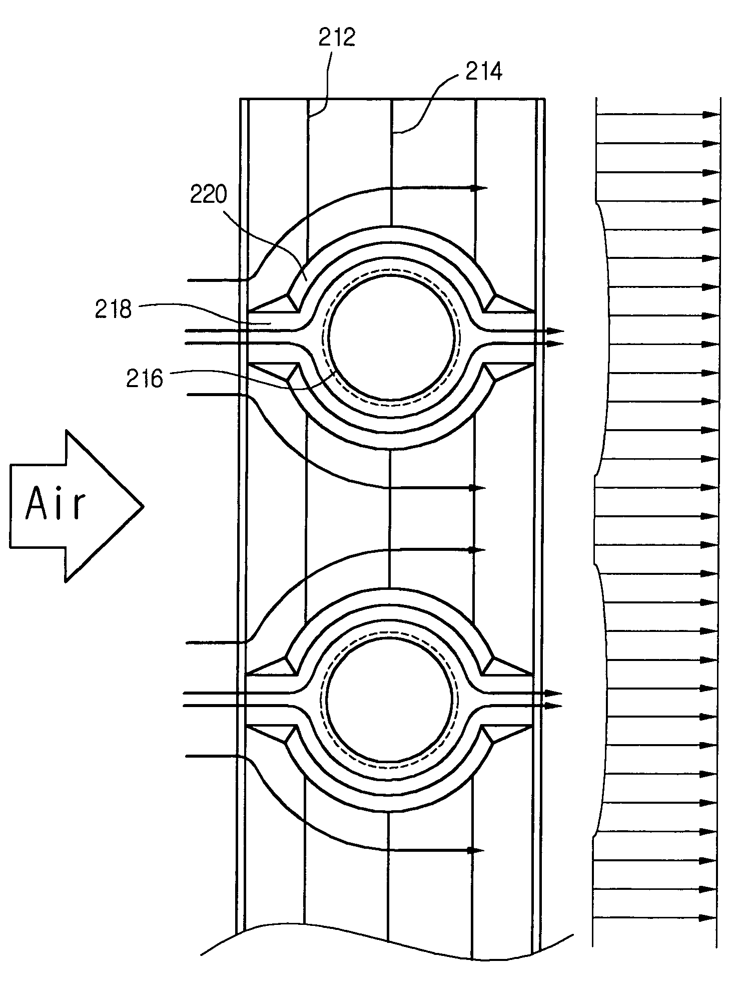
[0053] Referring to FIG. 7, a heat exchanger 201 includes a plurality of fins 210 spaced away from each other at a predetermined distance and a plurality of tubes 230, along which a refrigerant flow, disposed perpendicularly penetrating the fins 210 and spaced away from each other at a predetermined distance.

[0054] As shown in FIGS. 9A to 9C, the fin 210 includes peak and valley portions 212 and 214 that are alternately formed and connected to each other by inclined sections, collar portions 216 defining a tube insertion holes 216a through which the tubes 230 are inserted, longitudinal axes of the tubes being perpendicularly penetrating a longitudinal centerline of the fin 210, and seat portions 218 for s...


PUM


Abstract

Disclosed is a heat exchanger including a plurality of tubes through which refrigerants flow, the tubes being spaced away from each other, and a plurality of fins spaced away from each other at a predetermined distance. Each of the fins has fin collars through which the tubes are perpendicularly inserted, seat portions each concentrically formed around outer circumferences of the fin collars and provided with laterally-opened front and rear portions, more than two peak portions, and more than two valley portions, the peak and valley portions being alternately disposed to provide airflow variation.

Description

BACKGROUND OF THE INVENTION [0001] 1. Field of the Invention [0002] The present invention relates to a heat exchanger, and more particularly, to a heat exchanger that is designed to reduce flow-resistance of air introduced into a fin collar region of a corrugate fin and to provide a uniform airflow speed distribution to the fin. [0003] 2. Description of the Related Art [0004] Generally, a heat pump type air conditioner is operated in a cooling mode when an indoor temperature is higher than a predetermined level and is operated in a heating mode when the indoor temperature is lower than the predetermined level. At this point, when the air conditioner is operated in the heating mode, a heat exchanger of the air conditioner functions as an evaporator. [0005]FIG. 1 shows a conventional heat pump type air conditioner. [0006] Referring to FIG. 1, the heat pump type air conditioner is operated in cooling and heating modes according to an indoor temperature. [0007] In the cooling mode, refr...

Claims


Application Information

Patent Timeline
Patent Type & Authority Applications(United States)
IPC IPC(8): F28F1/10F25B39/00F28F1/32
CPCY10S165/504F28F1/32F28F1/10
Inventor OH, SAI KEEKO, CHEOL SOOJANG, DONG YEONSA, YONG CHEOLOH, SE YOONCHUNG, BAIK YOUNG
Owner LG ELECTRONICS INC
Why Eureka
Try Eureka