Gas-liquid contacting tray

Active Publication Date: 2005-03-03
SHELL OIL CO
View PDF24 Cites 14 Cited by
  • Summary
  • Abstract
  • Description
  • Claims
  • Application Information

AI Technical Summary

Benefits of technology

[0022] Suitable guiding means are guiding lips or guiding spouts, which are preferably attached to the sidewall near the outlet opening. A guiding spout or lip can e.g. be a planar, trough-like, or tubular. Preferably the guiding means is integrally

Problems solved by technology

It was observed that a problem occurs when such downcomers are operated at high liquid loads.
This is a problem since normally the liquid that is received on a certain tray must travel some distance to the next downcomer inlet opening so as to have sufficient residence time for gas-liquid contact on that tray.
This problem is not encountered when no perforations or valves are arranged in a liquid receiving area underneath the downcomers of the upper tray.
However this is undesirable since the unperforated liquid receiving area is arranged at the cost

Method used


Image

  • Gas-liquid contacting tray
  • Gas-liquid contacting tray
  • Gas-liquid contacting tray

Examples


example

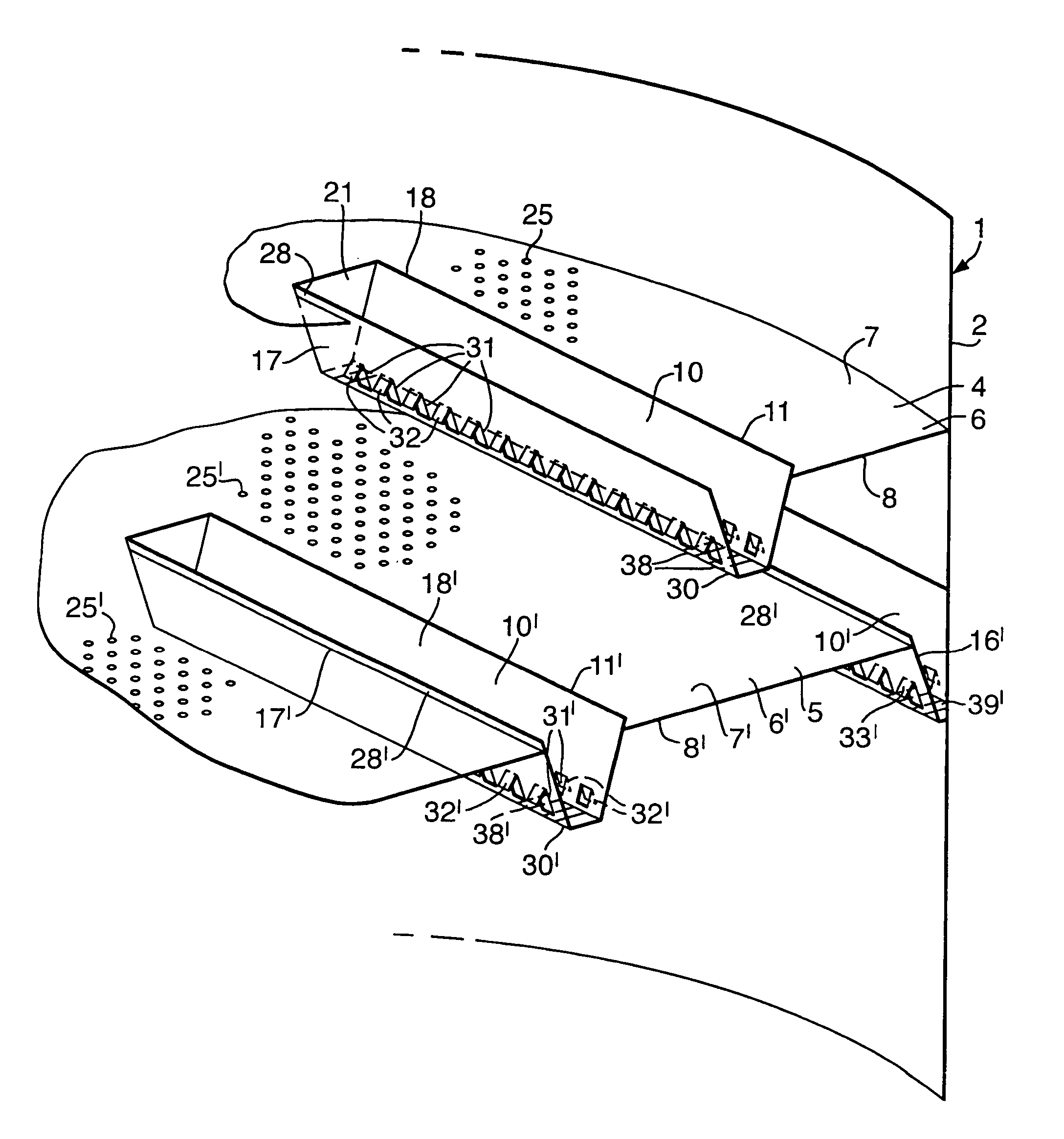
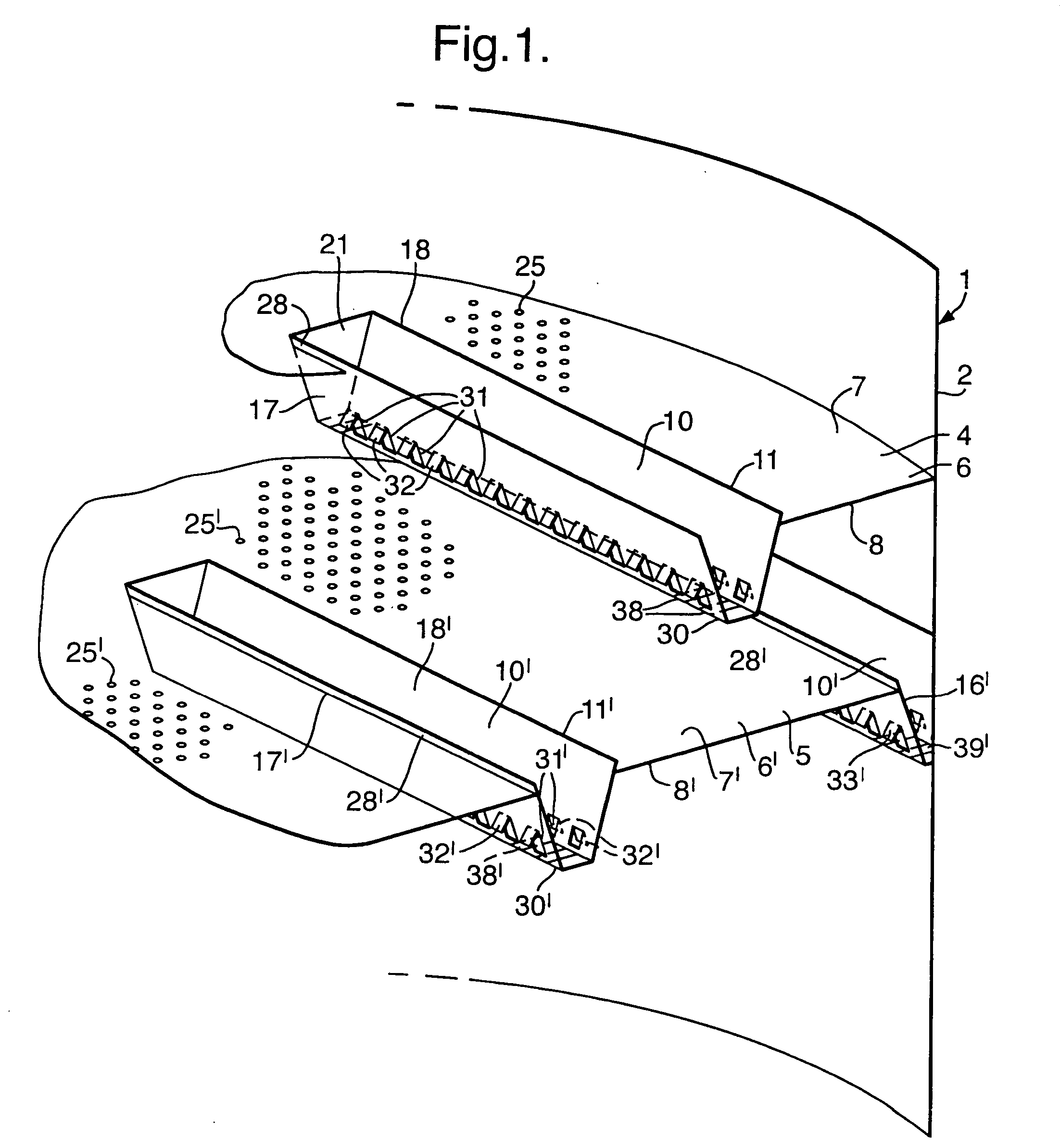
[0050] Consider a conventional rectangular sloped, truncated downcomer, having liquid outlet openings arranged in its bottom plate, in the form of a series of slots perpendicular to the elongated sidewalls. Liquid exiting the downcomer typically has an exit velocity ranging from 0.5 m / s to 1.5 m / s. The bottom plate of the truncated downcomer is typically 100 mm wide (measured perpendicular to the elongated sidewalls), and typically arranged 50-200 mm, in particular 100-200 mm above the level of the lower tray. Over this distance the liquid can distribute more or less evenly over the rectangular shaped volume directly underneath the bottom plate. Assume that the slots account for 50% of the area of bottom plate. Then, the liquid impacts on to the lower tray in the 100 mm wide area directly underneath the downcomer at an impact velocity which is a factor 2 lower than the exit velocity; in this case the impact velocity is typically 0.25 m / s-0.75 m / s. With such a high impact velocity it...


PUM


Abstract

A gas-liquid contacting tray suitable for horizontal mounting in a normally vertical column for counter-currently contacting gas and liquid, which tray comprises a tray plate having top and bottom surfaces, in which tray plate a downcomer inlet opening is arranged; and a downcomer for guiding liquid from the top surface of the tray plate to a downcomer outlet opening below the tray plate, which downcomer has a sidewall extending downwardly from the downcomer inlet opening, in which downcomer sidewall the liquid outlet opening is arranged, and wherein the liquid outlet opening is provided with a liquid guiding means.

Description

FIELD OF THE INVENTION [0001] The invention relates to a gas-liquid contacting tray, in particular to a such a tray comprising a tray plate having top and bottom surfaces, in which tray plate a downcomer inlet opening is arranged, and a downcomer for guiding liquid from the top surface of the tray plate to a downcomer outlet opening below the tray plate. BACKGROUND OF THE INVENTION [0002] Such a tray is normally horizontally mounted in a vertical column, and the terms upward, downward, top, and bottom are used in the specification and in the claims with reference to this normal tray arrangement. The vertical column can for example be a column for counter-currently contacting gas and liquid, such as a fractionation column, wherein a plurality of similar trays are vertically stacked. [0003] Each of such trays normally comprises a bubble area, which is an area on the tray plate that is provided with tray openings, e.g. perforations or special valves, through which gas can upwardly pass...

Claims


Application Information

Patent Timeline
IPC IPC(8): B01D3/20B01D53/18
CPCB01D53/18B01D3/20
Inventor SASTRY, ASHEESH VISWANATHA
Owner SHELL OIL CO
Why Eureka
Try Eureka