
Pry bar for lifting vending machines

a technology of lifting bars and vending machines, which is applied in the direction of children's carriages/perambulators, vehicles with one axis, hand carts, etc., can solve the problems of cumbersome and inefficient current methods of moving vending machines, and none of them is specifically designed for the ease of handling and effectiveness of use in connection with lifting vending machines, so as to prevent scratching or scraping, the effect of necessary strength and durability

Inactive Publication Date: 2005-03-03
GUNDERSON LLOYD E
View PDF39 Cites 9 Cited by
  • Summary
  • Abstract
  • Description
  • Claims
  • Application Information

AI Technical Summary

Benefits of technology

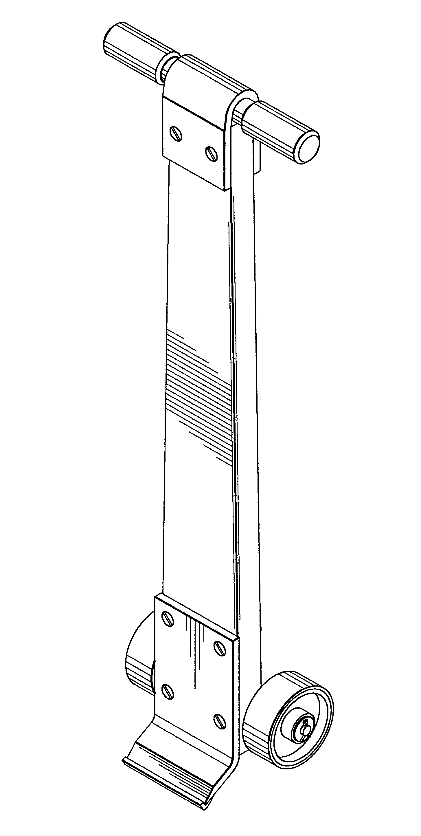
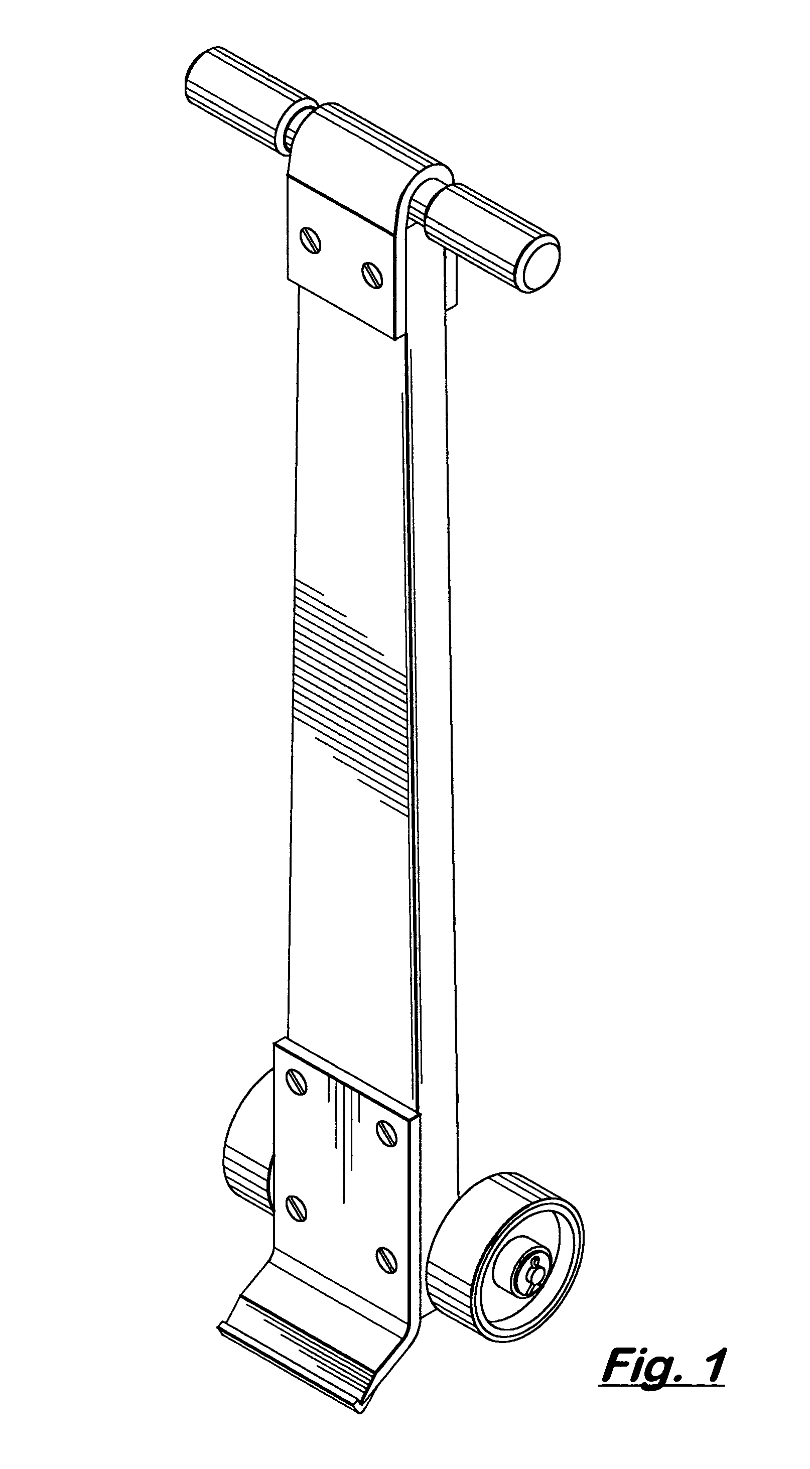
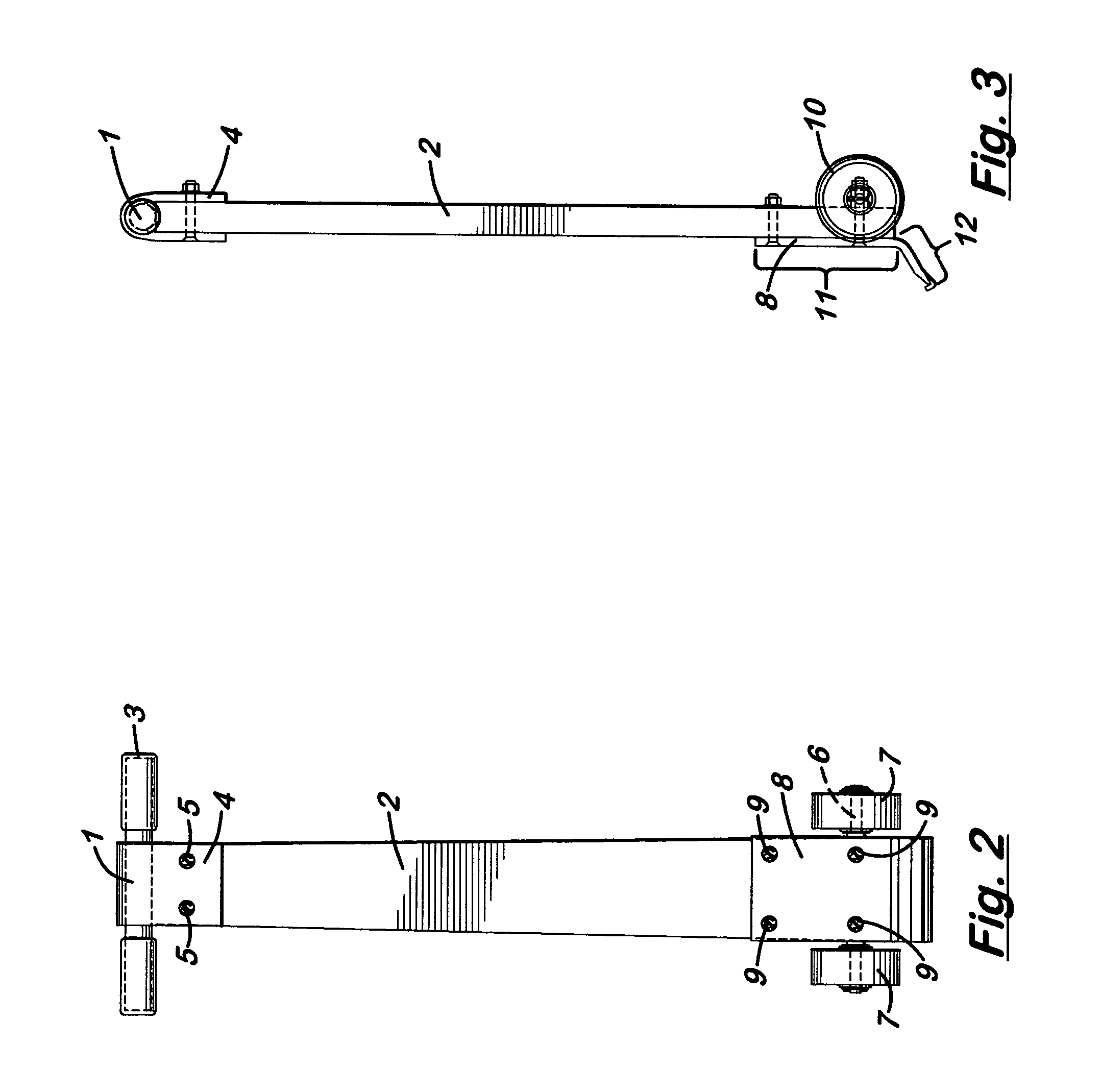
[0019] The present invention also provides that the handle is made of metal pipe and coated with a rubberized material for ease of grip, the rigid bar is tapered from bottom to top and made from a material selected from the group consisting of kiln dried wood, metal, fiberglass and phenolic plastic, all of which provide the necessary strength and durability. In the preferred embodiment, the wheel assembly comprises an axle, two wheels, a means for securing the wheels to the axle, and a means for securing the axle to the rigid bar, and the wheels are made of polyurethane to prevent scratching or scraping.

Problems solved by technology

Current methods of moving vending machines are cumbersome and inefficient.
The prior art includes numerous examples of lifting mechanisms, but none of them is specifically designed for the ease of handling and effectiveness of use in connection with lifting vending machines.
The only independent claim of this patent includes a limitation that relates to the facile dragging of stackable crates to different locations.

Method used


Image

  • Pry bar for lifting vending machines
  • Pry bar for lifting vending machines
  • Pry bar for lifting vending machines

Examples


Embodiment Construction

[0027] By virtue of its unique construction and design, the present invention can be carried easily by one person, allows a single person to safely move a vending machine in a matter of minutes, and can lift up to 5000 pounds. The preferred embodiment of the present invention has a “lip” that is specifically designed to catch the bottom of a vending machine. Because it is manually operated, the present invention is less expensive and easier to operate than hydraulic or other automatic lifts, and it does not require straps, chains or any other accoutrements. The present invention minimizes back injuries that can be caused by other lifting mechanisms because it allows a vending machine to be moved without the operator having to assume the full weight of the machine. The present invention is safe to use, simple in construction, yet strong and durable.

[0028] The following figures illustrate a preferred embodiment of the present invention:

[0029]FIG. 1 is a pictorial illustration of a p...


PUM


Abstract

An apparatus to facilitate the lifting of vending machines comprising a rigid bar, a handle attached to the rigid bar by a first metal plate, a second metal plate attached to the rigid bar with both a vertical and an oblique portion, and a wheel assembly. The oblique portion of the second metal plate comprises a flat section, a beveled edge, and a lip that engages the underside of the vending machine. The angle between the vertical and oblique portions of the second metal plate, the angle of the beveled edge, and the angle between the lip and the beveled edge are within specified ranges. The handle is coated with a rubberized material, the rigid bar is made from a material that provides the necessary strength and durability, and the wheels are made of polyurethane. A method of lifting a vending machine using the apparatus described herein.

Description

CROSS-REFERENCE TO RELATED APPLICATIONS [0001] This application is an original nonprovisional application. It does not claim priority back to any previously filed patent application.BACKGROUND OF THE INVENTION [0002] 1. Field of the Invention [0003] The present invention relates to the field of pry bars, hand trucks, dollies and similar mechanisms used to move heavy objects. In particular, the present invention is designed to lift vending machines for cleaning and maintenance purposes, or to position the machines so as to avoid vandalism or theft of the vending machine contents. [0004] 2. Description of the Related Art [0005] Vending machines need to be moved periodically so that a person can get behind the machine to perform maintenance on it or to clean behind it. The issue of cleaning behind vending machines is particularly important in schools, hospitals, grocery stores and similar locations where it is necessary or desirable to maintain a sanitary environment. Vending machines ...

Claims


Application Information

Patent Timeline
Patent Type & Authority Applications(United States)
IPC IPC(8): B62B1/14
CPCB62B1/14
Inventor GUNDERSON, LLOYD E.
Owner GUNDERSON LLOYD E
Learn More