Printing apparatus and dot position adjusting method
a technology of printing apparatus and dot position, which is applied in the direction of printing and other printing apparatus, can solve the problems of not all of the required patterns being printed on the print medium or a part, and the variation of the dot landing position
- Summary
- Abstract
- Description
- Claims
- Application Information
AI Technical Summary
Benefits of technology
Problems solved by technology
Method used
Image
Examples
embodiment 1
[0135] (Embodiment 1)
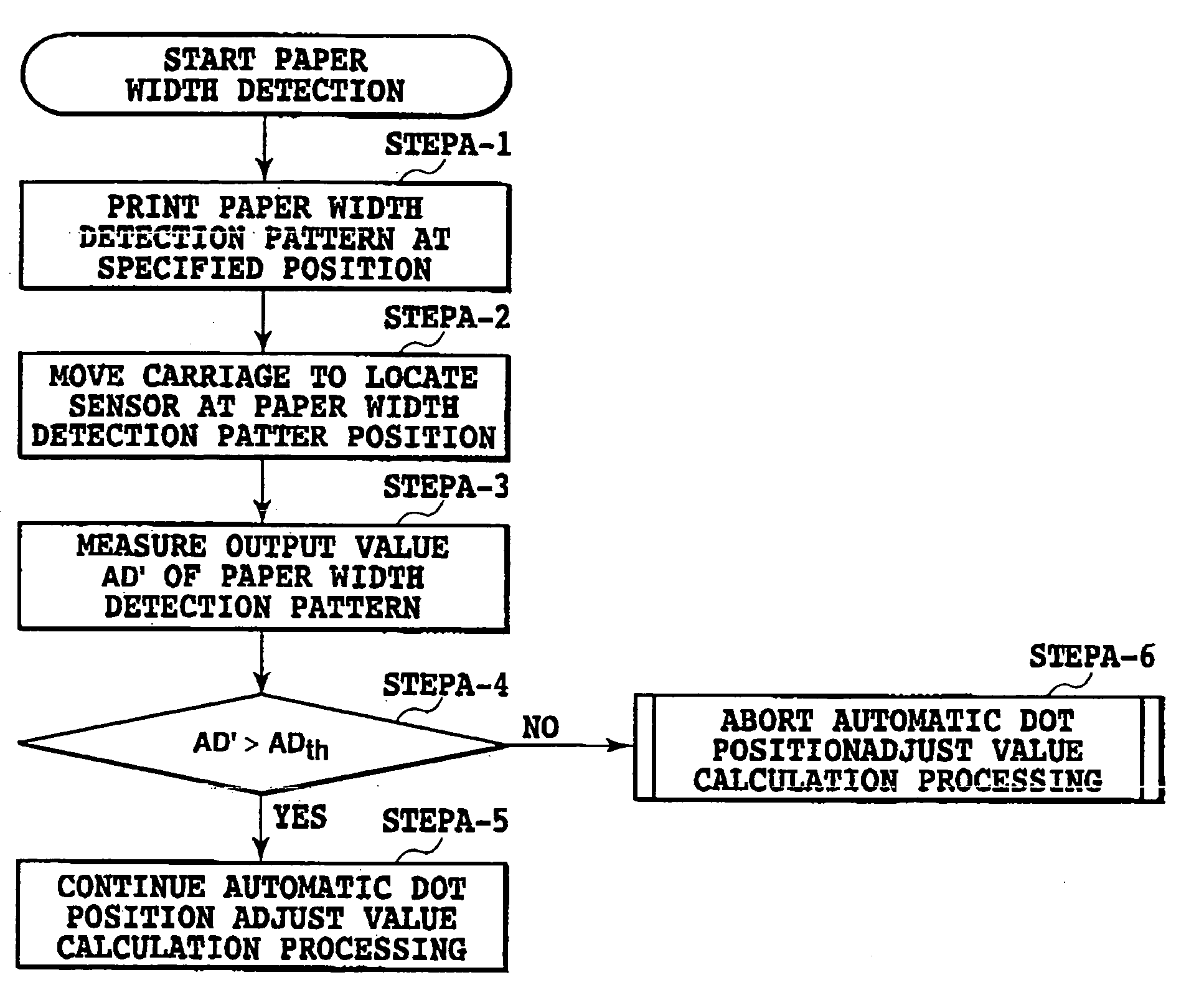
[0136] A construction characteristic of this invention will be described as Embodiment 1 in the following. In an ink jet printing apparatus with an optical sensor capable of automatic dot position adjust value calculation processing, before a test pattern for calculating a dot position adjust value is printed, a width of a print medium is detected to see if the print medium is wide enough to allow for normal dot position adjust value calculation processing.
[0137] The dot position adjust value calculation processing in this example is performed to obtain adjust values that are used to 1) in a printing apparatus that performs printing by reciprocally moving a carriage for scan, align print positions between dots formed by a forward printing and a backward printing, 2) in a print head that ejects a plurality of color inks, align print positions so that different color inks can land on the same position The dot position adjust value calculation processing is also r...
embodiment 2
[0151] (Embodiment 2)
[0152] Another construction characteristic of this invention will be described as Embodiment 2 in the following. As in the first embodiment, this embodiment detects the width of a print medium to see if the print medium has an enough width to perform the automatic dot position adjust value calculation processing normally. The second embodiment, however differs from the first embodiment in that not only is an output value of the test pattern measured but an output value of the print medium before it is printed with the test pattern is also measured. A difference between the two output values is used to correctly determine whether or not the test pattern has actually been printed.
[0153]FIG. 11 is a flow chart showing a sequence of steps performed by the printing apparatus of this embodiment to detect a paper width.
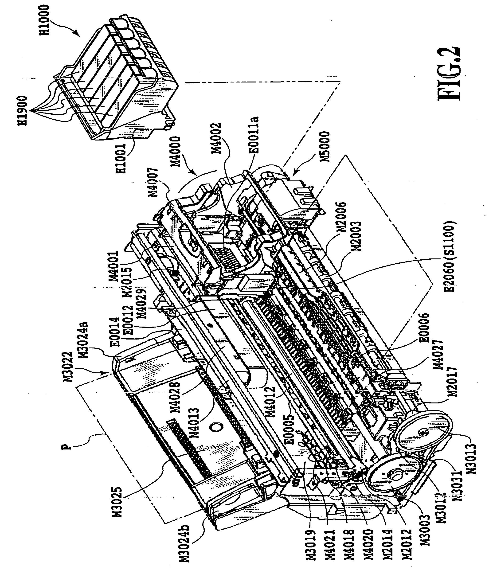
[0154] First, step B-1 moves the carriage and the print medium so that the optical sensor S1100 is situated at a position on the print medium supplied...
embodiment 3
[0167] (Embodiment 3)
[0168] A third embodiment of this invention will be described. In this embodiment also, the construction described in the first and second embodiment is applied. This embodiment is characterized in that, when an overall length of a plurality of nozzles in each nozzle array (a print width of a print head) is larger than a width of a platen absorbent, the paper width detection test pattern is printed by using only those nozzles situated directly above the platen absorbent.
[0169]FIG. 12 schematically shows a size relation among a platen, a platen absorbent and a print head in a printing apparatus that is applicable in this embodiment. In this embodiment, the width of the platen absorbent M2016 held between the two print medium support surfaces M2001a, M2001b is set to about 100 pixels as shown. Thus, ink droplets ejected onto an area 100 pixels wide are mostly absorbed by the platen absorbent M2016 and do not contaminate the interior of the apparatus. One pixel re...
PUM
 Abstract
Description
Claims
Application Information
 - R&D
- Intellectual Property
- Life Sciences
- Materials
- Tech Scout
- Unparalleled Data Quality
- Higher Quality Content
- 60% Fewer Hallucinations
Browse by: Latest US Patents, China's latest patents, Technical Efficacy Thesaurus, Application Domain, Technology Topic, Popular Technical Reports.
© 2025 PatSnap. All rights reserved.Legal|Privacy policy|Modern Slavery Act Transparency Statement|Sitemap|About US| Contact US: help@patsnap.com


