Multifunction transducer and method of driving
a multi-functional, transducer technology, applied in the direction of transducer details, telephone set construction, mechanical vibration separation, etc., can solve the problems of unpredictability of certain portable devices, inability to rigorously scrutinize such content for full compatibility, and size constraints
- Summary
- Abstract
- Description
- Claims
- Application Information
AI Technical Summary
Problems solved by technology
Method used
Image
Examples
first embodiment
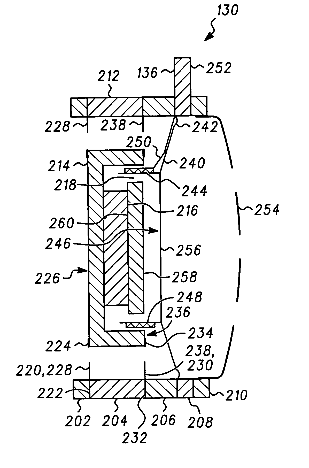
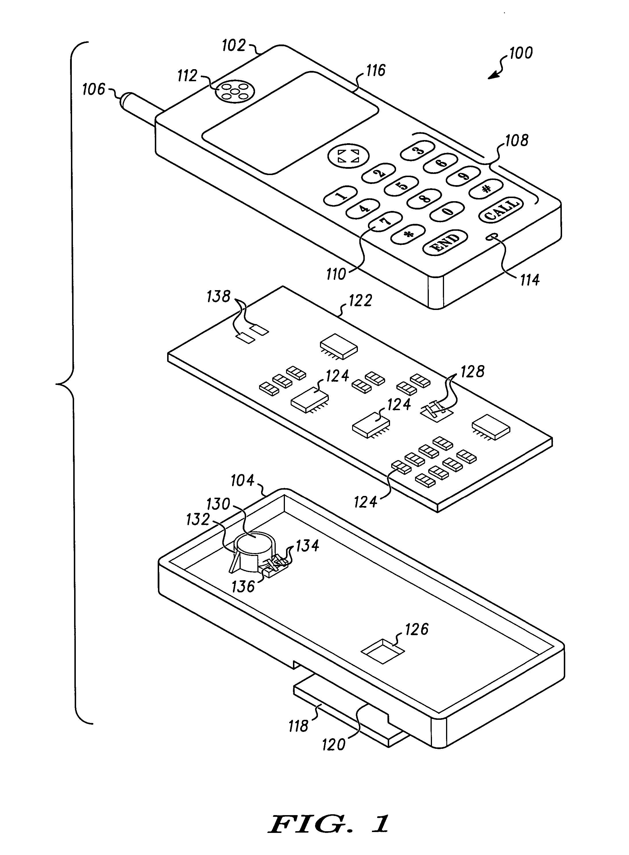
[0020]FIG. 1 is an exploded view of a cellular telephone 100 according to the invention. The cellular telephone 100 comprises, a front housing part 102, and a rear housing part 104. The front housing part 102 supports and antenna 106 and includes an array of openings 108 that accommodate keys of a keypad 110. A speaker grill 112 and a microphone grill 114 are also provided on the front housing part 102. A display opening 116 is also including in the front housing part 102. A battery compartment cover 118 is provided for covering a battery compartment 120 in the rear housing part 104.
[0021] The front 102, and rear 104 housing parts enclose a circuit board 122. In FIG. 1 the back side of the circuit board 122 is visible. A plurality of electrical circuit components 124, that make up one or more electrical circuits of the cellular telephone 100 are mounted on the circuit board 122. Circuits of the cellular telephone 100 are more fully described below with reference to a functional bloc...
second embodiment
[0044]FIG. 7 is a perspective view of a MFT 700 according to the invention and FIG. 8 is a magnified view of a portion of the MFT shown in FIG. 7. The MFT 700 includes a flat beam piezoelectric transducer motor 702. A first end 701 of the flat beam 702 is provided with two through holes 704 that are used to mount the MFT 700. A mass 706 is supported at a second end 703 of the beam 702. The second end 703 of the beam 702 is free to move. A first electrical contact 708, and a second electrical contact 728 are located proximate the first end 701 of the beam 702. A twisted pair leads 218 (not shown in FIG. 7) are soldered to the first and second contacts 708, 728. Other types of electrical connections can be used in lieu of the twisted pair of leads.
[0045] The beam 702 includes a plurality of layers as will be described presently. A first outer mylar layer 710 forms one side of the beam 702, and a second outer mylar layer 712 forms an opposite side of the beam 702. A first silver film l...
PUM
 Abstract
Description
Claims
Application Information
 - R&D
- Intellectual Property
- Life Sciences
- Materials
- Tech Scout
- Unparalleled Data Quality
- Higher Quality Content
- 60% Fewer Hallucinations
Browse by: Latest US Patents, China's latest patents, Technical Efficacy Thesaurus, Application Domain, Technology Topic, Popular Technical Reports.
© 2025 PatSnap. All rights reserved.Legal|Privacy policy|Modern Slavery Act Transparency Statement|Sitemap|About US| Contact US: help@patsnap.com


