
Computer system and cluster system program

a computer system and cluster system technology, applied in the field of computer systems, can solve problems such as the inability to optimally allocate services to the computer

Inactive Publication Date: 2005-03-03
KK TOSHIBA
View PDF6 Cites 46 Cited by
  • Summary
  • Abstract
  • Description
  • Claims
  • Application Information

AI Technical Summary

Benefits of technology

[0010] According to one aspect of the present invention, there is provided a computer system having two or more computers connected to each other, comprising: a policy managing section which changeably stores policy information for determining processing of allocating a plurality of services executed by the computers; an optimal service allocation section which executes processing of allocating each service to an optimal computer according to the policy information; and a service relocation section which executes processing of relocating a service allocated by the optimal service allocation section by referring to the policy information in accordance with a state of executing a service between the computes.

Problems solved by technology

Further, the cluster system uses a reserved computer (provisioning computer) when all the initially set computers are established in a high load state, and there is no optimal computer for allocating a service in the initially set computers.
Specifically, when automatic service switch-over is executed, there has been a circumstance that switch-over occurs frequently with a load change; what action to be taken is not clear when a low priority service is previously executed; or startup is not carried out when there is no computer which is capable of executing a service.

Method used


Image

  • Computer system and cluster system program
  • Computer system and cluster system program
  • Computer system and cluster system program

Examples


first embodiment

[0021] (First Embodiment)

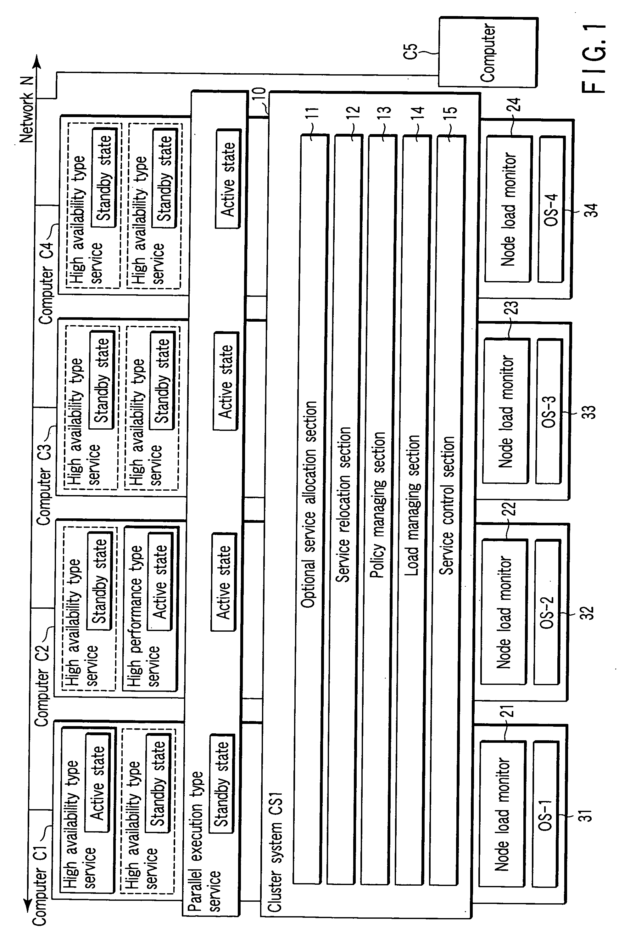
[0022]FIG. 1 is a block diagram depicting a system configuration of a computer system according to a first embodiment of the present invention.

[0023] In the computer system, for example, four computers C1 to C5 are configured to be mutually connected to one another over a network N. With the computers C1 to C5, computers C1 to C4, for example, are so set that each operates under the control of operating systems (OS-1 to OS-4). Here, the computer C5 is a reserved computer (provisioning computer) which is connected to the computer system via the network N. One or more reserved computers may be connected to the network N in addition to the computer C5.

[0024] A cluster system is configured by the computers C1 to C4. In this cluster system, a cluster control section (CS1) 10 operates. The cluster control section 10 is a virtual machine achieved by a cluster control program (cluster software) (not shown) provided in each of the computers C1 to C4 integrally oper...

second embodiment

[0089] (Second Embodiment)

[0090] FIGS. 3 to 5 are block diagrams depicting a system configuration of a computer system according to a second embodiment of the present invention and changes of the system configuration shown in FIG. 3.

[0091] As shown in FIG. 3, a computer system in an initial state is configured so that, for example, five computers C1 to C5 are interconnected with one another over a network N. Further, a sixth computer C6 is connected over the network N. The computer C6 is set in a stopped state at first, and is registered in a provisioning computer pool 60 as a provisioning computer (reserved computer).

[0092] The provisioning computer pool 60 is conceptually illustrated so that one or more initially stopped computers are registered as provisioning computers, and is defined as a generic name.

[0093] Registering a provisioning computer in the provisioning computer pool 60 denotes registering information (such as a processor name or a MAC address, for example) concern...


PUM


Abstract

In a computer system which achieves a cluster system using two or more computers, a cluster control section has an optimal service allocation section which assigns a service to an optimal computer in accordance with policy information, and a service relocating section which executes relocation of a service according to a change of a load state of the each computer.

Description

CROSS-REFERENCE TO RELATED APPLICATIONS [0001] This application is based upon and claims the benefit of priority from prior Japanese Patent Application No. 2003-310161, filed Sep. 2, 2003, the entire contents of which are incorporated herein by reference. BACKGROUND OF THE INVENTION [0002] 1. Field of the Invention [0003] The present invention generally relates to a computer system composed of a plurality of computers, and more particularly, to a technique of a cluster system which achieves an optimal service allocation function according to a failure or load state of a computer. [0004] 2. Description of the Related Art [0005] In recent years, there has been developed software technology called a cluster system which manages a computer system composed of a plurality of computers (for example, a server) and which enhances service processing performance and reliability to be provided at a client terminal (user) by executing an application program. The cluster system has a function for...

Claims


Application Information

Patent Timeline
Patent Type & Authority Applications(United States)
IPC IPC(8): G06F9/50H04L29/06H04L29/08
CPCG06F9/5088H04L69/329H04L67/32H04L29/06H04L67/60H04L9/40
Inventor MIZOGUCHI, KENICHI
Owner KK TOSHIBA
Learn More