Adhesive roller

a technology of adhesive rollers and rollers, which is applied in the direction of cleaning apertures in pipes, household cleaners, and domestic applications, can solve the problems of affecting the cleaning effect, so as to achieve the effect of maximizing cleaning efficiency and easy separation from the roller

Inactive Publication Date: 2005-03-10
THE EVERCARE
View PDF15 Cites 3 Cited by
  • Summary
  • Abstract
  • Description
  • Claims
  • Application Information

AI Technical Summary

Benefits of technology

[0014] An adhesive coating is then applied across substantially all of a first or outer side of the backing layer. Thereafter, an adhesive release coating covers at least a portion of a second or inner side of the backing layer and this release coating has a release strength which varies laterally across the strip. Consequently, after the strip is wound into a cylindrical roller with the adhesive layer facing outwardly, the adhesive release coating between the backing layer and the next inner adhesive sheet reduces the adhesion between the backing layer and the next inner adhesive sheet thus allowing the sheets to easily separate from the roller when desired. Some adhesion, however, between the backing layer and the next inner adhesive sheet is necessary in order to maintain the integrity of the roller in use.
[0015

Problems solved by technology

After prolonged use of the adhesive roller for cleaning surfaces, the adhesive on the outermost adhesive layer or sheet of the adhesive roller becomes covered with detritus and other matter and loses its adhesiveness.
However, because of the adhesion of the backing strip with the adhesive on the next underlying layer on the roller, the actual removal of single sheets, each constituting one circumference of the roller, is oftentimes difficult.
Frequently, the outermost sheet of the adhesive roller becomes torn during its removal.
Even though a uniform release coating covers the side of the backing strip opposite from the adhesive side, these previously known uniform release coatings, however, are of a relatively weak strength in order to ensure the integrity of the roll in use.
Even with these previously known adhesive rollers having both spaced perforations and/or a cut formed through the roller to facilitate separ

Method used


Image

  • Adhesive roller
  • Adhesive roller
  • Adhesive roller

Examples


Embodiment Construction

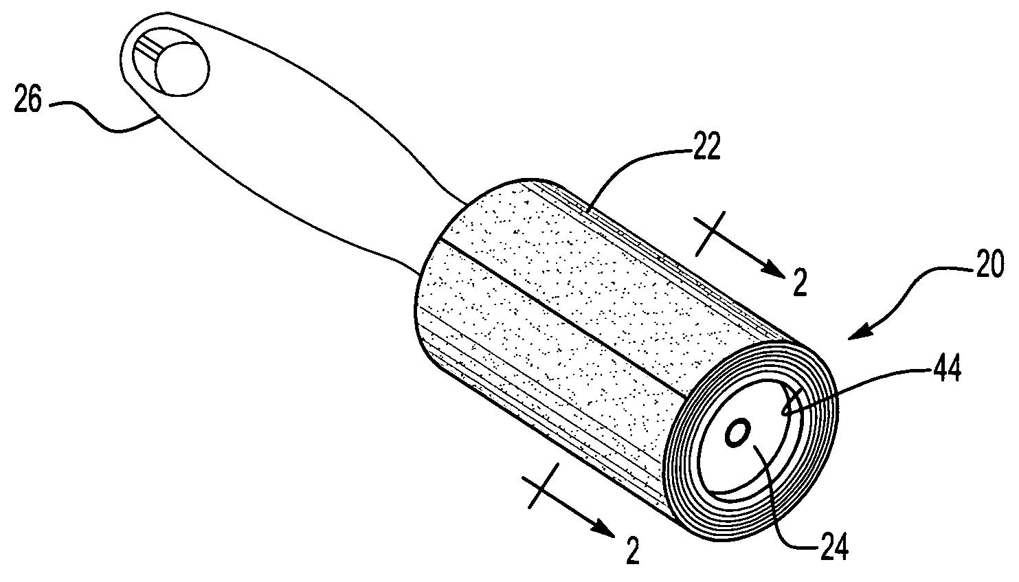
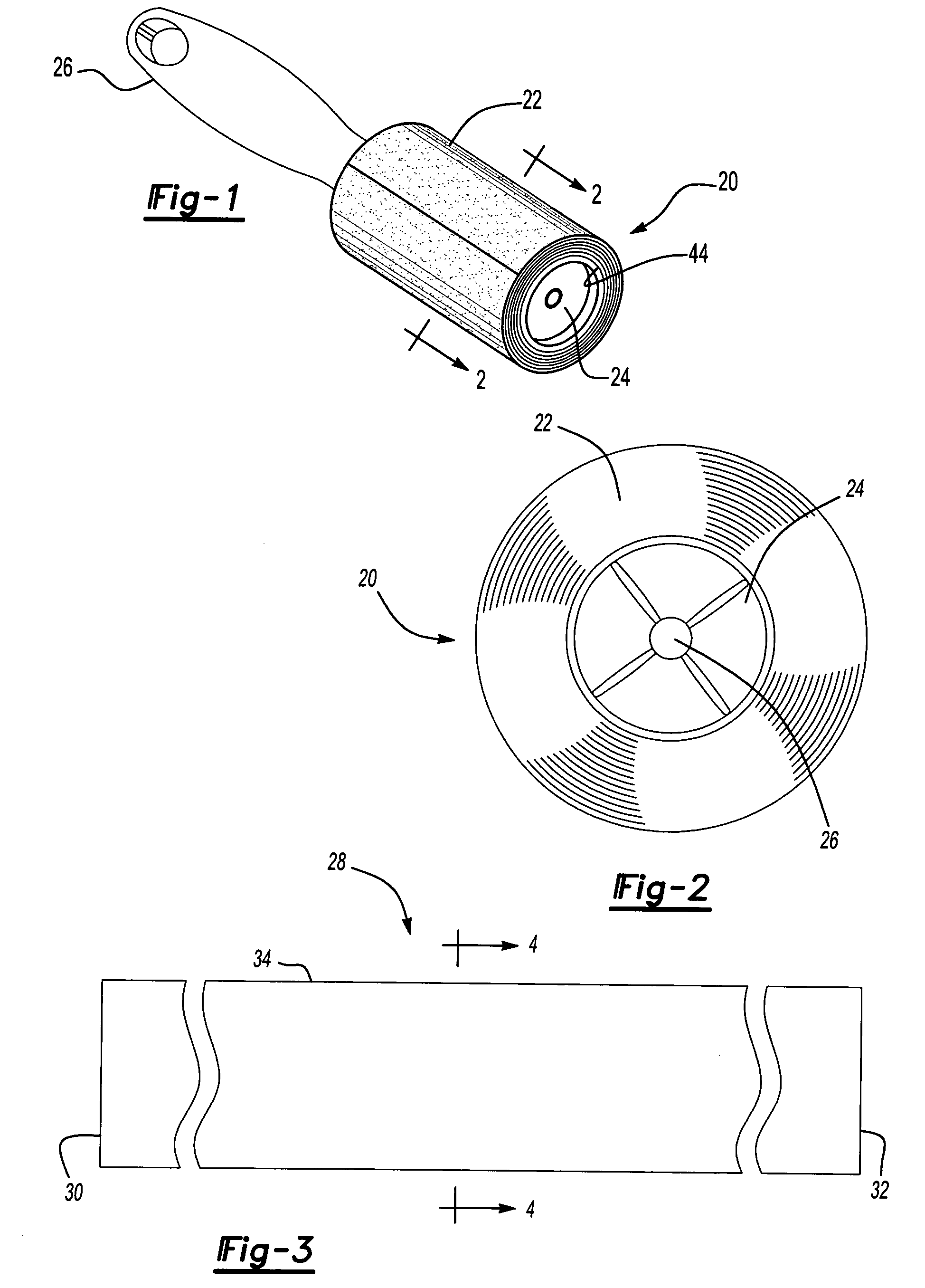
[0035] With reference first to FIGS. 1 and 2, a first preferred embodiment of the adhesive roller 20 of the present invention is shown in which the roller 20 is tubular and cylindrical in shape. The roller 20 preferably includes a tubular and cylindrical core 24 made of cardboard, plastic or other suitable material. The core 24 is then mounted on a handle 26 (FIG. 1) so that the adhesive roller 20 rotates freely with respect to the handle 26.

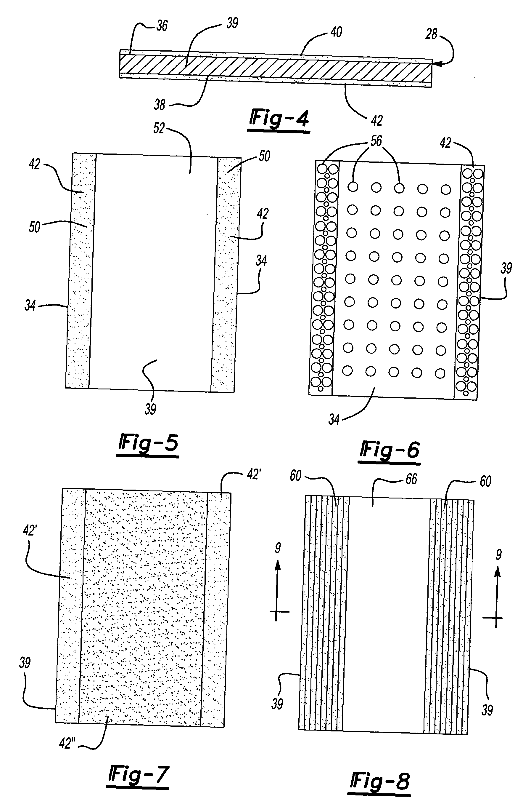
[0036] With reference now to FIGS. 3 and 4, the adhesive roller 20 comprises an elongated strip 28 having a first end 30, a second end 32, and two spaced apart and generally parallel sides 34. As best shown in FIG. 4, the strip 28 includes a backing layer 39 having a first or outer side 36 and second or inner side 38. The backing layer 39 may be constructed of any conventional material, such as paper. Additionally, the backing layer 39 may be made of paper, film, cloth, foam as well as other materials and mixtures thereof. In the event that the...


PUM


Abstract

An adhesive roller for detritus removal having an elongated strip where the strip has both a backing layer and an adhesive layer overlying and covering a first side of the backing layer. The strip also has a first end, a second end and two spaced apart sides. The strip is wound from its first end and to its second end into a tubular cylindrical roller with the adhesive layer facing outwardly. An adhesive release coating also overlies at least a portion of a second side of the backing layer. The adhesive release coating may be either applied as a liquid coating, or may be a solid substrate. This adhesive release coating facilitates removal of individual sheets from the roller. Alternatively, a portion of the backing layer is crimped to form alternating peaks and valleys along at least a portion of the backing layer. These alternating peaks and valleys limit the amount of areal contact between the backing layer and the next inner adhesive layer of the roller to facilitate removal of individual sheets from the roller.

Description

BACKGROUND OF THE INVENTION [0001] I. Field of the Invention [0002] The present invention relates generally to adhesive rollers of the type used for detritus removal. [0003] II. Description of Related Art [0004] There are many previously known adhesive rollers used for detritus removal. These previously known rollers typically comprise an elongated strip having a backing layer. The strip includes two ends and two spaced apart and parallel sides. [0005] An adhesive layer is provided along a first side of the backing layer. Thereafter, the strip is wound into a tubular and cylindrical roller with the adhesive layer facing outwardly. Oftentimes the strip is wound around a tubular core and the tubular core is then rotatably mounted on a handle to facilitate rolling of the adhesive roller along the surface desired to be cleaned. [0006] After prolonged use of the adhesive roller for cleaning surfaces, the adhesive on the outermost adhesive layer or sheet of the adhesive roller becomes cov...

Claims


Application Information

Patent Timeline
IPC IPC(8): A47L25/00
CPCA47L25/005
Inventor MCKAY, NICHOLAS D. JR.SCHMIDT, MARK
Owner THE EVERCARE
Why Eureka
Try Eureka