Tip tool

a tip and tool technology, applied in the field of tip tools, can solve the problems of deficient methods, small tips, and irreparable damage to the optical elements of the tip, and achieve the effect of accurate manipulation of the tip and easy manipulation of the tip

Inactive Publication Date: 2005-03-10
GE INSPECTION TECH LP
View PDF43 Cites 63 Cited by
  • Summary
  • Abstract
  • Description
  • Claims
  • Application Information

AI Technical Summary

Benefits of technology

[0011] In a further aspect of the invention, a tip tool is provided which allows for attaching and / or detaching a tip to an imaging apparatus without damaging the tip.
[0012] In yet another aspect of the invention, a tip tool is provided which allows for easy manipulation of the tip in poor lighting conditions.
[0013] In another aspect of the invention, a tip tool is provided which allows for accurate manipulation of a tip by a user when the user is wearing gloves or other protective gear.
[0014] In a further aspect of the invention, a tip tool is provided which allows for attaching and / or detaching a tip without soiling the tip.

Problems solved by technology

All of these methods are deficient, for several reasons.
Thus dropping the tip, or worse, crushing the tip by using an inappropriate tool, may irreparably damage the optical elements of a tip or lose the tip altogether.
Depending on the imaging apparatus employing the tip, the tip also may be small, and difficult to manipulate by hand.
For users with visual impairments, such as farsightedness, or for users operating in less than ideal conditions, such as in a sewer system or a dimly lit garage, accurately manipulating the optical tip may be difficult.
In environments where protective gear or gloves are required, such as those dealing with hazardous substances or in medical / surgical procedures (in the case of an endoscope), manipulation of an optical tip may be even more unmanageable.
Touching the tip also may create problems, especially if dirt, chemicals, and / or oils from a fingertip or glove smudge the optical interface of the tip.
Such inadvertent soiling of the tip may lead to degraded images and / or damaged tips.

Method used


Image

  • Tip tool
  • Tip tool
  • Tip tool

Examples


Embodiment Construction

[0021] It is to be understood that the invention is not limited in its application to the details of construction and arrangements of components set forth herein in the detailed description of the preferred embodiment or illustrated in the drawings. The invention is capable of other embodiments and of being practiced or being carried out in various ways.

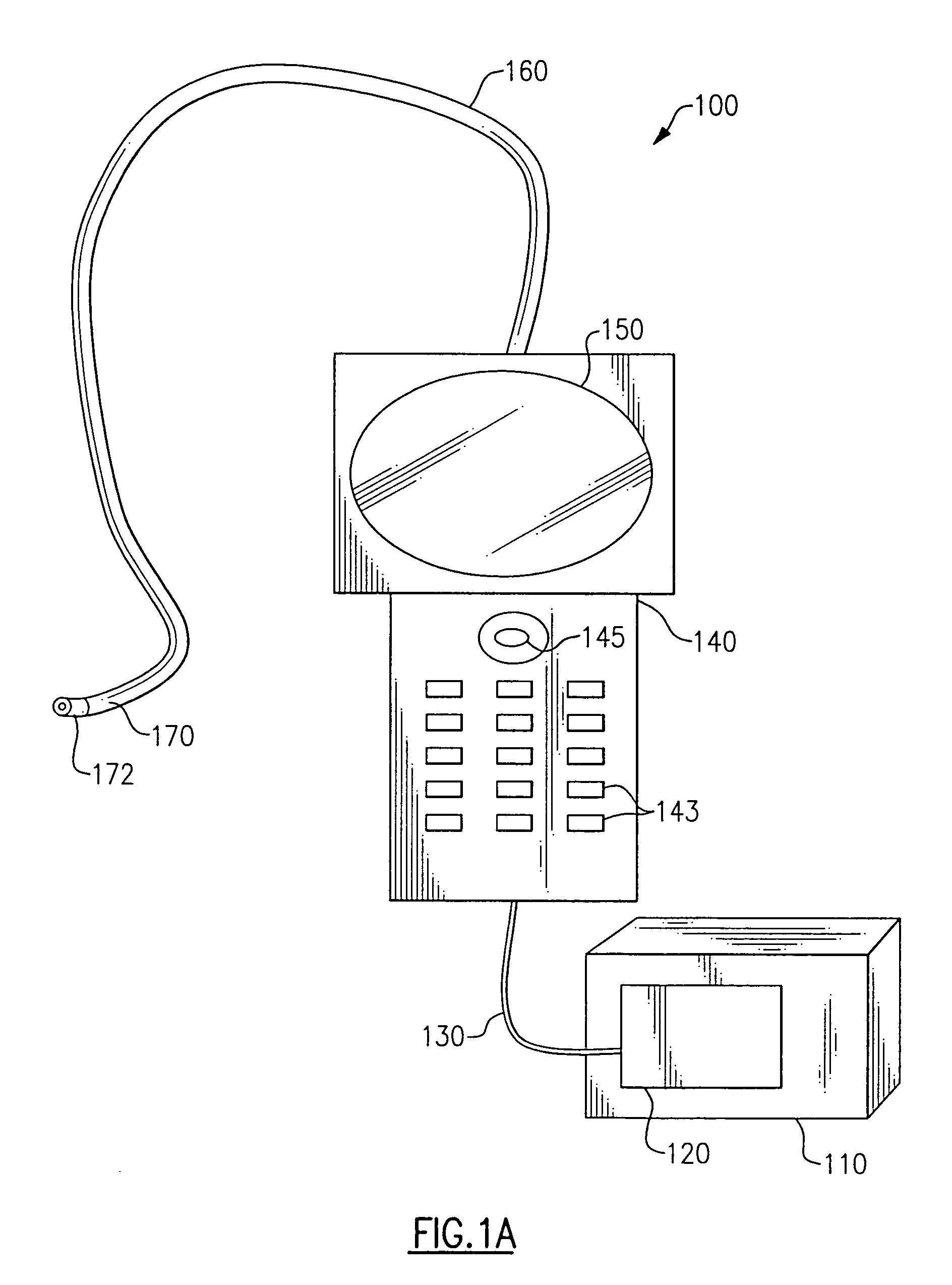
[0022] Referring to FIG. 1A, a typical imaging device 100 (a boroscope in the illustrative embodiment) according to the invention is illustrated, such as is sold by Everest VIT® of Flanders, N.J. Such a device could include, as shown in the illustrative embodiment, a portable shipping / operating case 110, which includes a power supply 120 for the device and a light source, such as a metal halide arc lamp (not shown). The shipping / operating case 100 is shown in operative communication with a handpiece 140 by means of a tethered cable 130. The handpiece 140 can include, by way of example, an LCD monitor 150 (which displays images seen ...


PUM

PropertyMeasurementUnit
diameteraaaaaaaaaa
diameteraaaaaaaaaa
diameteraaaaaaaaaa

Abstract

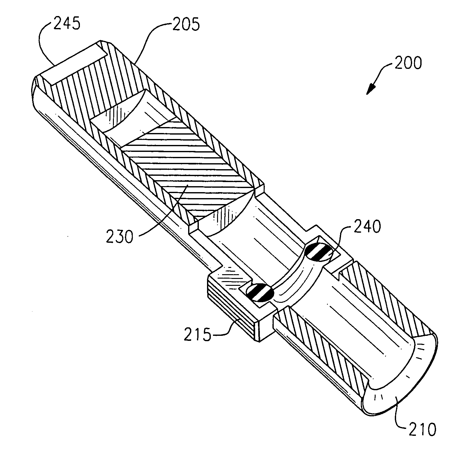
A tip tool, and methods for using the tip tool to either connect or disconnect a tip to / from an imaging apparatus, are provided. The tip tool includes a body sized to fit over at least a portion of the tip and a tip holding element disposed in contact with the tip tool body for releasably engaging the tip.

Description

CROSS REFERENCE TO RELATED APPLICATIONS [0001] None. FIELD OF THE INVENTION [0002] The invention relates generally to methods and devices for connecting a tip to, or disconnecting a tip from, an imaging apparatus. BACKGROUND OF THE INVENTION [0003] Modern digital inspection systems, such as borescopes and endoscopes of the type available from Everest VIT®, of Flanders, N.J., often employ insertion tubes or other devices to image locations that are remote or not easily, if at all, accessible. Such locations can include, but are not limited to, industrial targets, such as the interior of pressure vessels, turbines, reactors, and the like, or medical targets, such as within body lumens or surgical incisions among others. A distal end of such insertion tubes may be designed to employ a tip which contains various functional elements (usually optical), and which may be interchangeable and removably connected to the insertion tube. In the alternative, the tip may be intended for permanent ...

Claims


Application Information

Patent Timeline
Patent Type & Authority Applications(United States)
IPC IPC(8): A61B1/00B25B9/00B25B9/02G02B23/24
CPCB25B9/00B25B9/02G02B23/2484A61B1/00101Y10T29/49822A61B1/00131Y10T29/49815Y10T29/53683Y10T29/49826A61B1/00105
Inventor SCOTT, JOSHUA LYNNROBERTS, RANDY HOWARDFISH, CHARLES W. III
Owner GE INSPECTION TECH LP
Why Eureka
Try Eureka