Power tool work table

a technology of power tools and work tables, applied in the field of work tables, can solve the problems of heavy tables with limited cutting paths, limited size of existing work tables,

Inactive Publication Date: 2005-03-10
ZHANG CHARLIE
View PDF13 Cites 19 Cited by
  • Summary
  • Abstract
  • Description
  • Claims
  • Application Information

AI Technical Summary

Benefits of technology

[0006] It is one object of this invention to provide a work table that is lightweight and portable yet still includes a significant work surface.

Problems solved by technology

Existing work tables are typically limited in size by weight and portability considerations.
This arrangement results in a heavy table with a limited cutting path.

Method used


Image

  • Power tool work table
  • Power tool work table
  • Power tool work table

Examples


Embodiment Construction

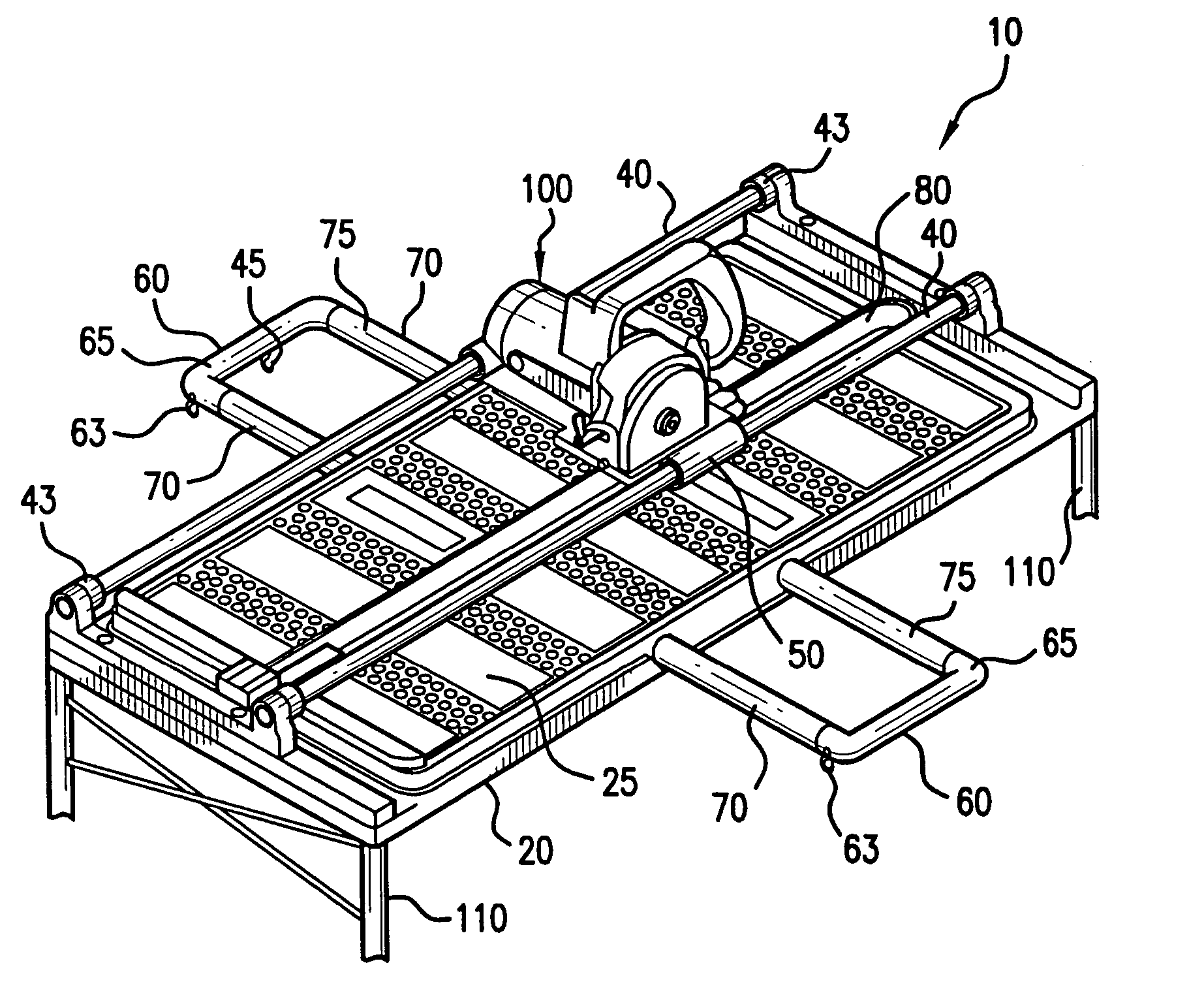
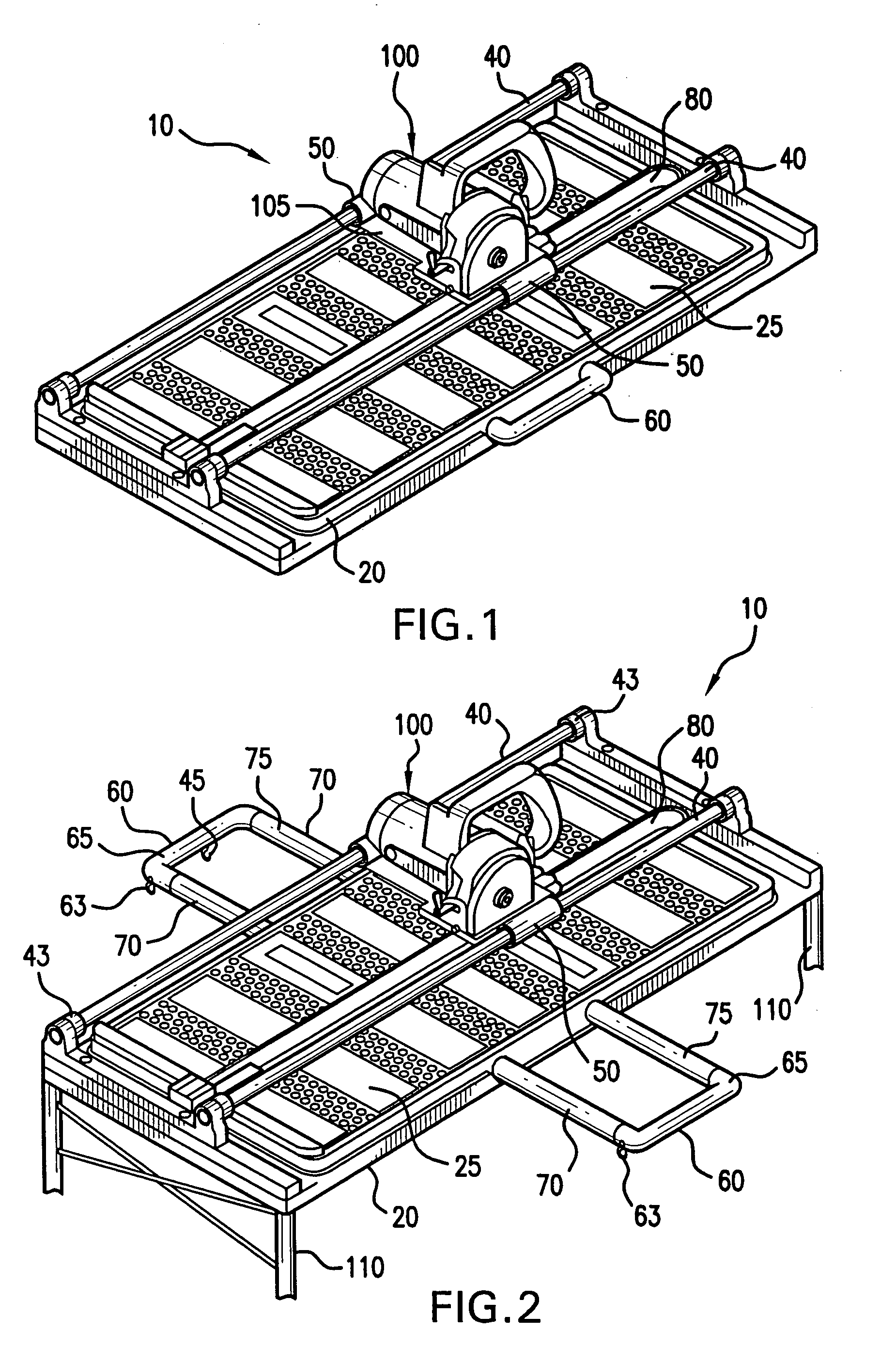
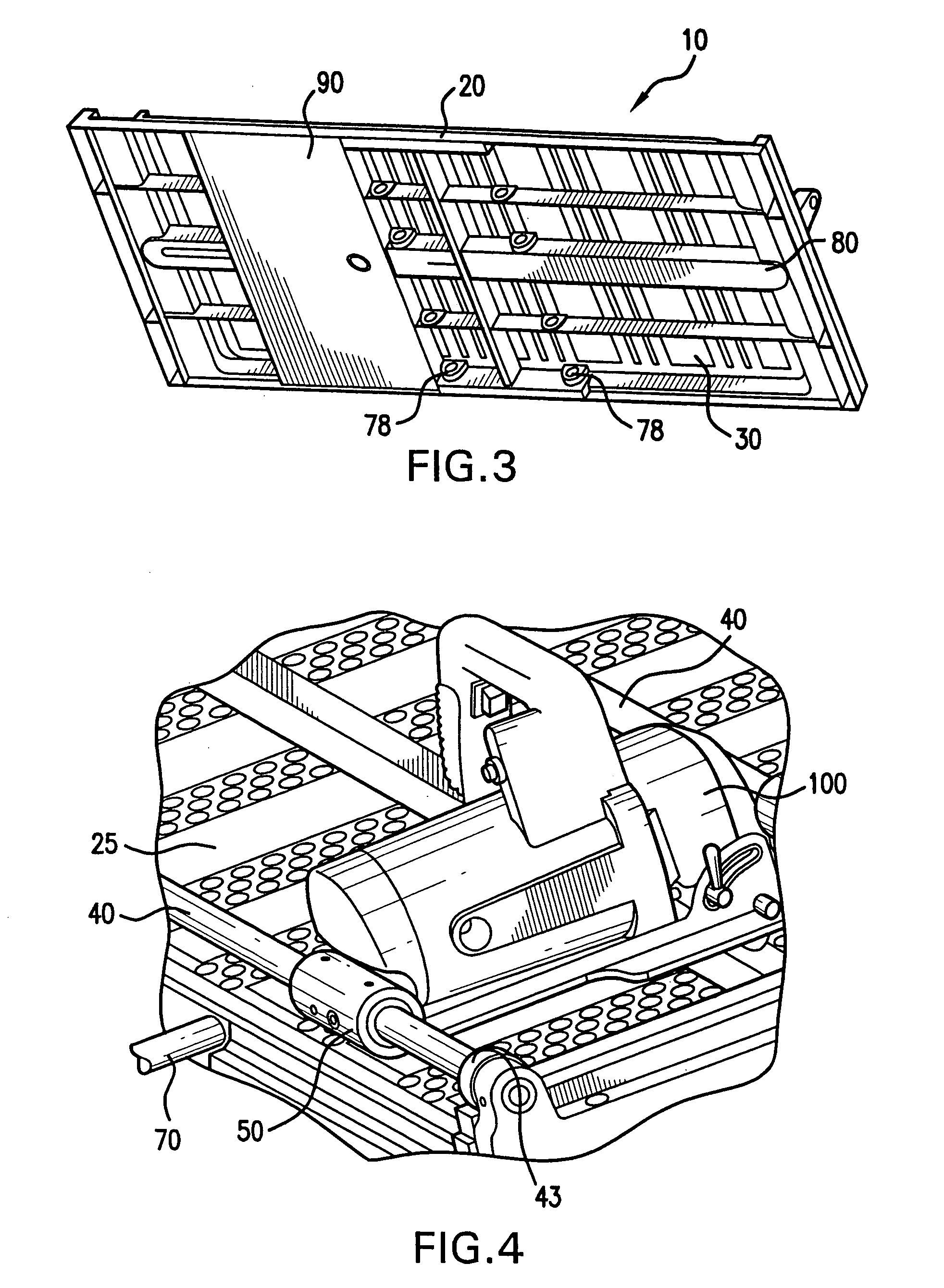
[0021]FIGS. 1-5 show a work table 10 according to one preferred embodiment of this invention.

[0022] Work table 10 preferably includes a planar member 20 having a generally flat work surface 25 and an opposed lower surface 30. Work surface 25 is preferably configured to accommodate materials for cutting, grinding, sanding, etc. As such, work surface 25 may include an integrated grid spaced at desired units of measure.

[0023] As shown in FIGS. 1 and 2, two generally parallel bars 40 extend across or along a length of work surface 25. According to one preferred embodiment of this invention bars 40 are constructed of aluminum or other suitable strong, lightweight material. Bars 40 preferably extend longitudinally across work surface 25 and preferably include bumpers 43 at each end to dampen impact of a power tool against each end of bar 40.

[0024] Further, work table 10 preferably includes sleeve 50 slidably connected around each bar 40. Sleeves 50 preferably comprise a bushing, a bear...


PUM

PropertyMeasurementUnit
obtuse angleaaaaaaaaaa
lengthaaaaaaaaaa
depthaaaaaaaaaa

Abstract

A work table including a water tray defining a reservoir, and forming a ridge at least partially positioned within the reservoir and extending along a length of the water tray. A planar member having a work surface is positionable with respect to the water tray, and forms a channel extending through the work surface. The channel is aligned with the ridge and in fluid communication with the reservoir with the planar member positioned on the water tray.

Description

BACKGROUND OF THE INVENTION [0001] 1. Field of the Invention [0002] This invention relates to a work table for using a power tool, such as a tile saw. [0003] 2. Description of Related Art [0004] Work tables are useful on job sites requiring portable work surfaces for cutting, machining and otherwise processing construction materials. Existing work tables are typically limited in size by weight and portability considerations. [0005] One example of existing work tables are tables having an overhead bar under which a power tool travels to effect a straight path for cutting, grinding, etc. This arrangement results in a heavy table with a limited cutting path. SUMMARY OF THE INVENTION [0006] It is one object of this invention to provide a work table that is lightweight and portable yet still includes a significant work surface. [0007] It is another object of this invention to provide a work table that can provide a steady supply of water or similar coolant to a power tool. [0008] It is y...

Claims


Application Information

Patent Timeline
Patent Type & Authority Applications(United States)
IPC IPC(8): B23Q9/00B23Q11/10
CPCB23Q11/10B23Q9/00Y10T83/929
Inventor ZHANG, CHARLIE
Owner ZHANG CHARLIE
Why Eureka
Try Eureka