Method and apparatus for gas displacement well systems

a technology of gas displacement and well system, applied in the field of well system, can solve the problems of increasing the diameter increasing the size of the purge pump, and increasing the size of the return line, and achieve the effect of reducing the purge volume of the well

Inactive Publication Date: 2005-03-10
BLAISDELL MARK KEVIN
View PDF2 Cites 89 Cited by
  • Summary
  • Abstract
  • Description
  • Claims
  • Application Information

AI Technical Summary

Benefits of technology

[0026] A method and apparatus is provided for reducing the purge volume of a well during purging and sampling operations. In some system embodiments, the apparatus can be retrofitted to existing small diameter wells, typically wells 2 inches or less in diameter, and piezometers. A further embodiment provides a method and apparatus for using direct pneumatic pressure to purge and sample small diameter wells using a removable valve. This aspect of the invention allows a primary valve of a direct pneumatic pressure pump, i.e. gas displacement pump to be withdrawn through the top of the inside of a pressure holding structure (typically the riser pipe), without removing the riser pipe or the system's primary inlet structure, e.g. filter, screen, or other external fluid entry ports. The invention allows fitting or retrofitting small diameter we

Problems solved by technology

When Barcad systems are buried directly in a borehole, removal is not possible, and can be difficult when a BARCAD® system is placed inside of a well.
A limit for such purge pumps is that the diameter of the return line represents a set of trade offs.
These problems become more significant with increasing pumping depth which is one reason such pumps are generally used at shallow depths, typically 250 feet or less.
The disclosed prior art systems and methodologies thus provide sampling and purging systems for well structures, but fail, in those cases where the riser pipe is part of the pump

Method used


Image

  • Method and apparatus for gas displacement well systems
  • Method and apparatus for gas displacement well systems
  • Method and apparatus for gas displacement well systems

Examples


embodiment 163

[0117] As well, the preferred use of valve control 163 can reduce the quantity of gas 155 used in operating the system 100e. In a basic control embodiment 163, a technician can close a valve 161 on a line 138 as air is observed exiting a line 138. In alternate control embodiments 143, the control 163 comprises mechanical and / or electronic detectors which automatically actuate one or more valves 161 to close off one or more respective lines 138, after detecting air in the respective lines 138. While the valves 161 and controls 163 can be located anywhere on the lines 138, the valves 161 and controls 163 would typically be located at or near the ground surface GS and / or discharge end of the lines 138.

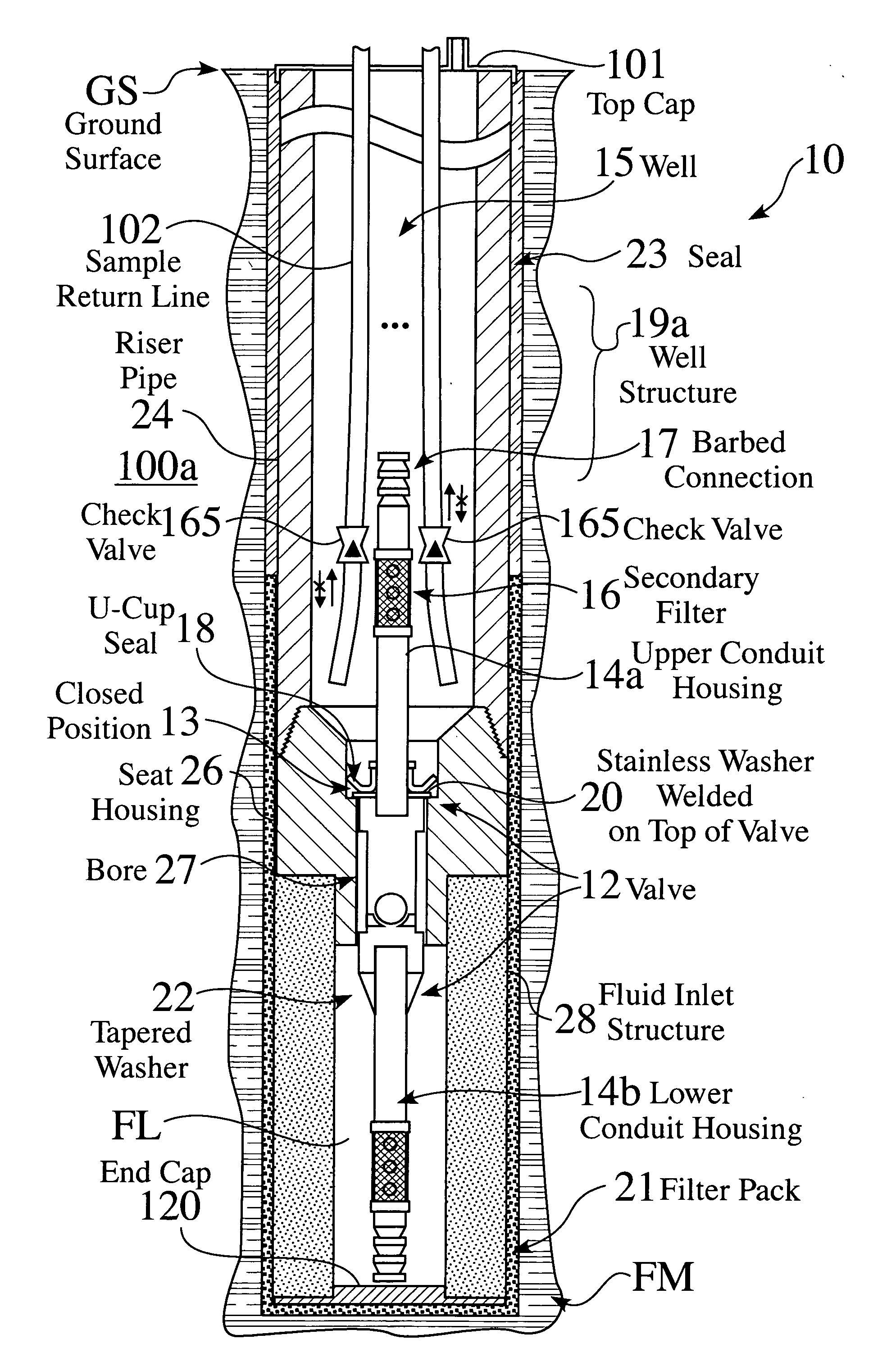
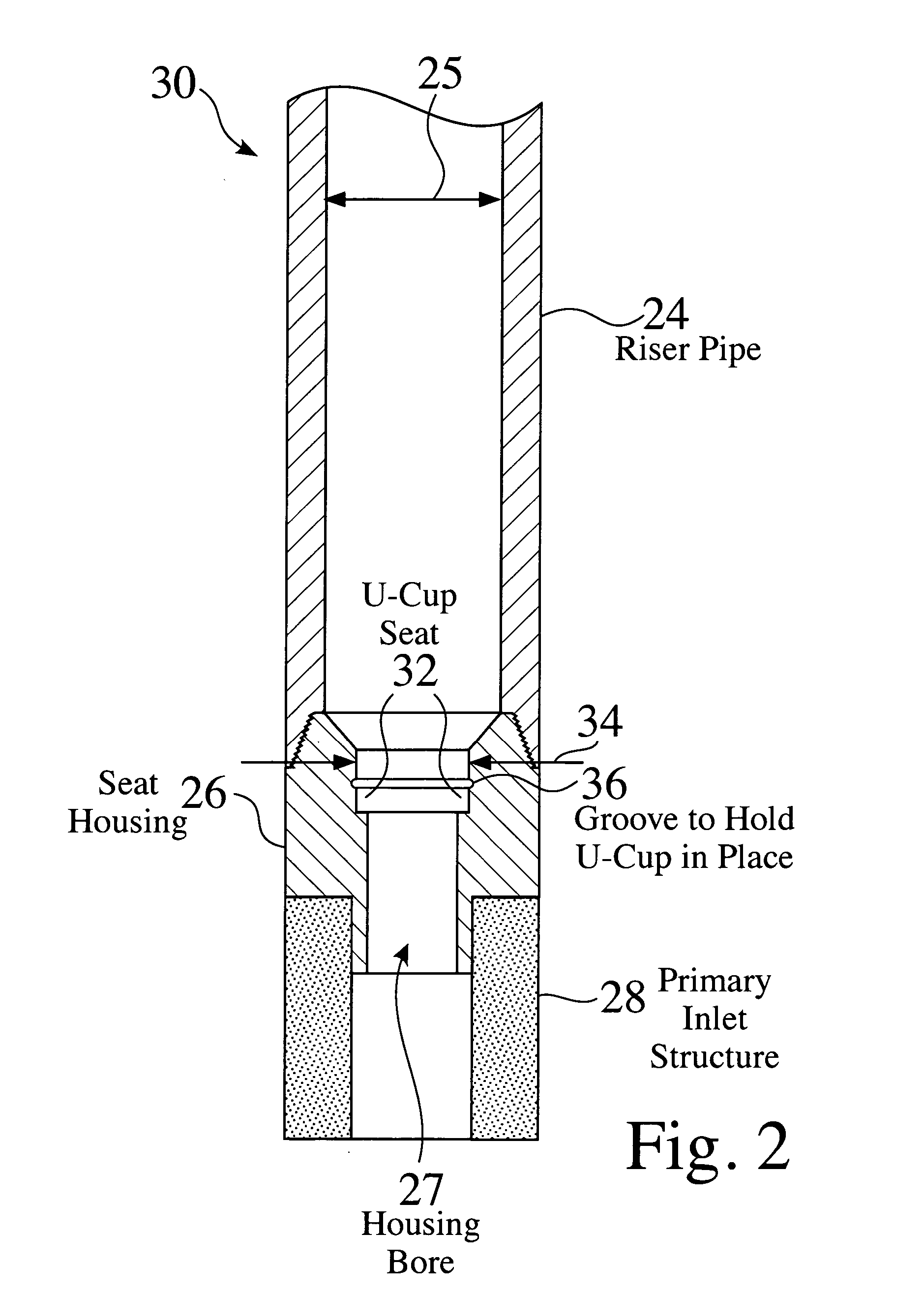
[0118] The direct pneumatic pressure pumping method provides a one-way check valve above the screened interval of a well, typically a narrow diameter well, so that the blank casing of the well becomes the outer housing of the pneumatic pump. This structure may also be used as a pump place...

embodiment 26

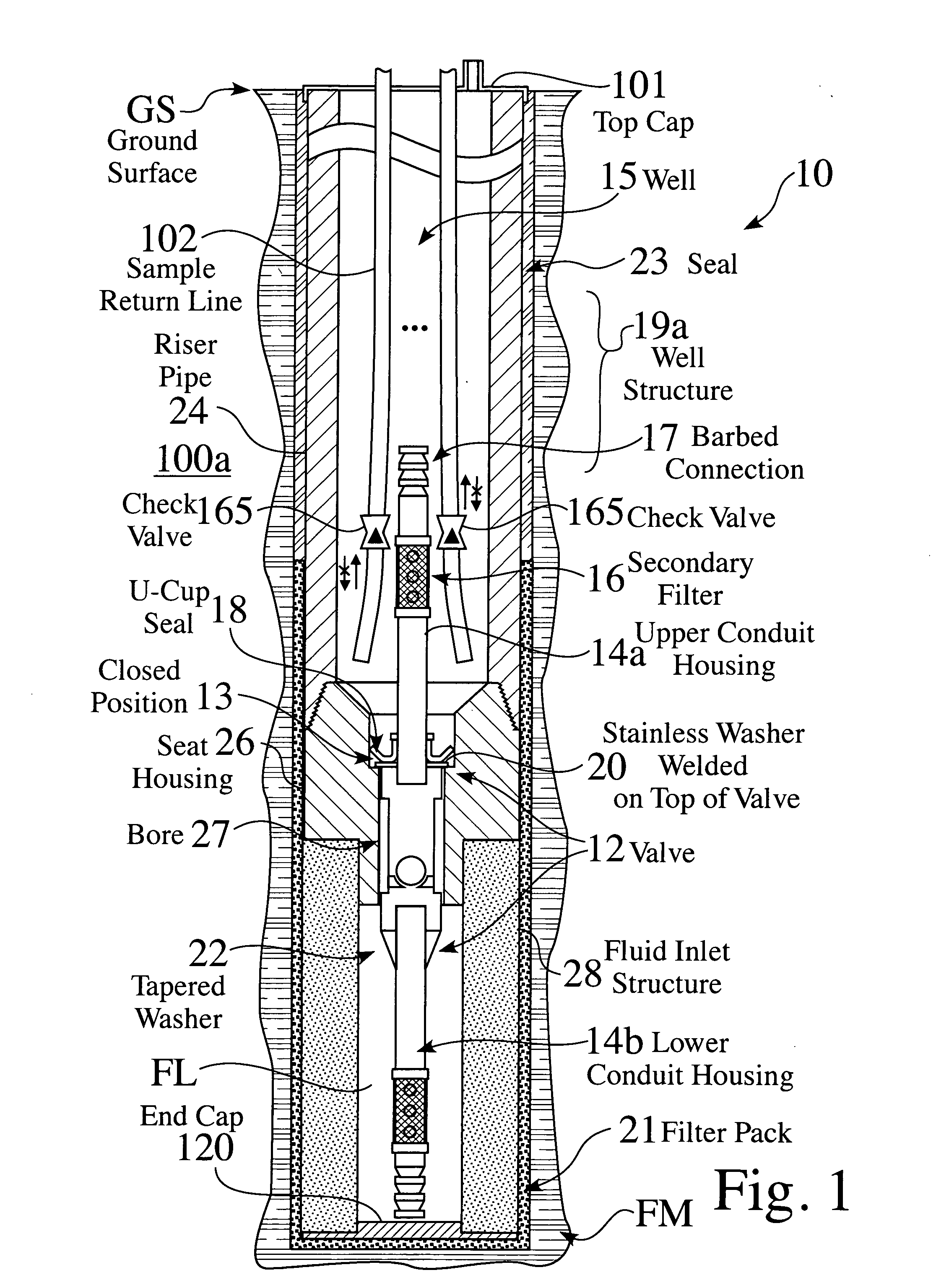
[0122] As seen in FIG. 21, upon direct, i.e. pneumatic, pressurization 224, the u-cup seal 18 rests on the seat 32, to form a sealed connection 226a. As seen in FIG. 22, without direct pressurization 224, the u-cup seal 18 floats on the seat 32, to form a open passage 226b, which allows water FL to refill the riser pipe 24, by flowing between the u-cup seal 18 and seat 32. In the exemplary housing embodiment 26 shown in FIG. 21 and FIG. 22, the seat housing 26 does not include a central valve or a groove in the seat 32 to hold the u-cup 18 onto the seat 32.

[0123] The sample return line shown in FIG. 21 and FIG. 22 includes a support structure 222 attached to its lower end 227, which is designed such that the lower edge 227 preferably rests on the ledge constriction 202 above the seat 32, and allows the solid plug / guide 210 to move up 252 (FIG. 22) enough to allow water FL to flow up around the u-cup seal 18. The plug guide 210 is preferably comprised of lightweight materials, so as ...


PUM


Abstract

A method and apparatus is provided for reducing the purge volume of a well during purging and sampling operations. In some system embodiments, the apparatus can be retrofitted to existing small diameter wells. A further embodiment provides a method and apparatus for using direct pneumatic pressure to purge and sample small diameter wells using a removable valve. This aspect of the invention allows a direct pneumatic pressure pump with a primary valve to be withdrawn through the top of the inside to the pump's pressure holding structure without removing a riser pipe or the system's fluid inlet structure. The invention allows fitting or retrofitting small diameter wells with valves for direct pneumatic pressure purging and sampling. Other embodiments include sealing a removable valve at or above the bottom of a riser pipe, remotely attaching a tool at the top of a removable valve, withdrawing a direct pneumatic pressure pump system's primary valve through the inside of the inside pump's pressure holding structure without removing the riser pipe, and attaching a direct pneumatic pressure pump system's sample return line to its primary valve. Further embodiments include a multiple return line pneumatic pump/well, which allows the use of multiple return lines on a pneumatic pump when used to pump water from very deep wells where piezometric surface of the water is also deep, as well as other uses for direct pressure pneumatic pumping and sampling.

Description

CROSS-REFERENCE TO RELATED APPLICATIONS [0001] This application claims priority from BLAI0001PR, U.S. Provisional Patent Application Ser. No. 60 / 489,049, filed 21 Jul. 2003 and from BLAI0002PR, U.S. Provisional Patent Application Ser. No. 60 / 489,262, filed 21 Jul. 2003, which are incorporated herein by reference.FIELD OF THE INVENTION [0002] The invention relates to the field of well systems. More particularly, the invention relates to improved well structures and processes. BACKGROUND OF THE INVENTION [0003] It is commonly preferred that the fluid from a well be sample or purged. Several systems and methods have been disclosed for sampling and purge systems for well environments. [0004] M. Lebourg, Fluid Sampling Apparatus, U.S. Pat. No. 3,104,713 (24 Sep. 1963) discloses “an apparatus for obtaining a representative fluid sample of a fluid flowing in a well when taken at a given depth and at the same time giving the amount of fluid flowing at a given time”. [0005] M. Dean, L. Castr...

Claims


Application Information

Patent Timeline
IPC IPC(8): E21B49/08F04B
CPCE21B49/084
Inventor BLAISDELL, MARK KEVIN
Owner BLAISDELL MARK KEVIN
Why Eureka
Try Eureka