
Escapement system

Active Publication Date: 2005-03-10
AIRWAY AUTOMATION
View PDF2 Cites 19 Cited by
  • Summary
  • Abstract
  • Description
  • Claims
  • Application Information

AI Technical Summary

Benefits of technology

[0008] The present inventive escapement assembly provides fasteners and the like quickly and economically to an associated manufacturing system in a proper orientation while assuring a high probability of proper alignment, thereby increasing efficiency and reducing scrap rates of the resultant parts. The escapement assembly results in reduced manufacturing costs, is capable of a long operating life, and is particularly well adapted for the proposed use.

Problems solved by technology

As a result, a significant number of nuts are fed to the welding machine in an improper orientation due to false reading during the initial check.

Method used


Image

  • Escapement system
  • Escapement system
  • Escapement system

Examples


Embodiment Construction

[0016] For purposes of description herein, the terms “upper,”“lower,”“right,”“left,”“rear,”“front,”“vertical,”“horizontal,” and derivatives thereof shall relate to the invention as oriented in FIGS. 3-5. However, it is to be understood that the invention may assume various alternative orientations and step sequences, except where expressly specified to the contrary. It is also to be understood that the specific devices and processes illustrated in the attached drawings, and described in the following specification are exemplary embodiments of the inventive concepts defined in the appended claims. Hence, specific dimensions and other physical characteristics relating to the embodiments disclosed herein are not to be considered as limiting, unless the claims expressly state otherwise.

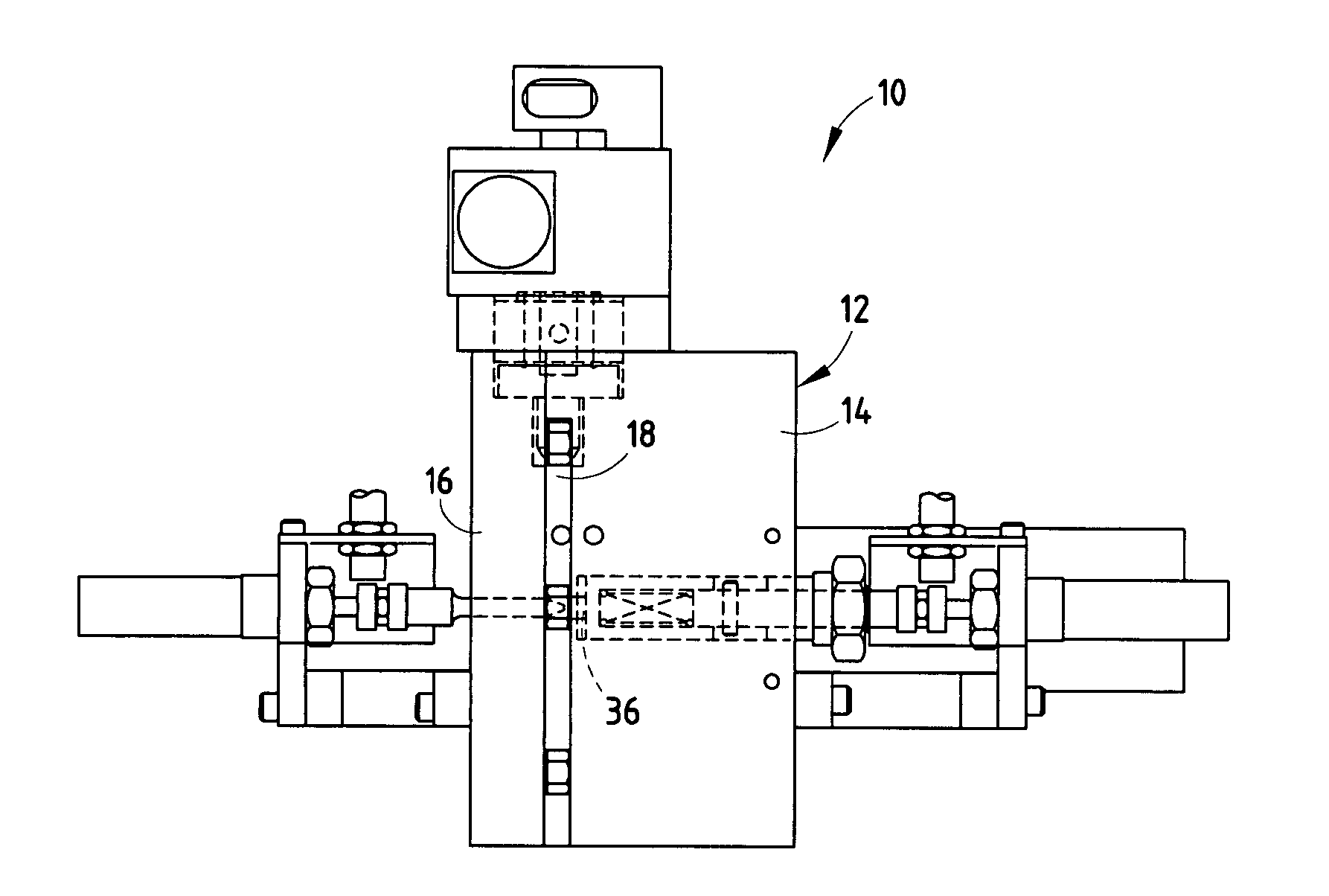
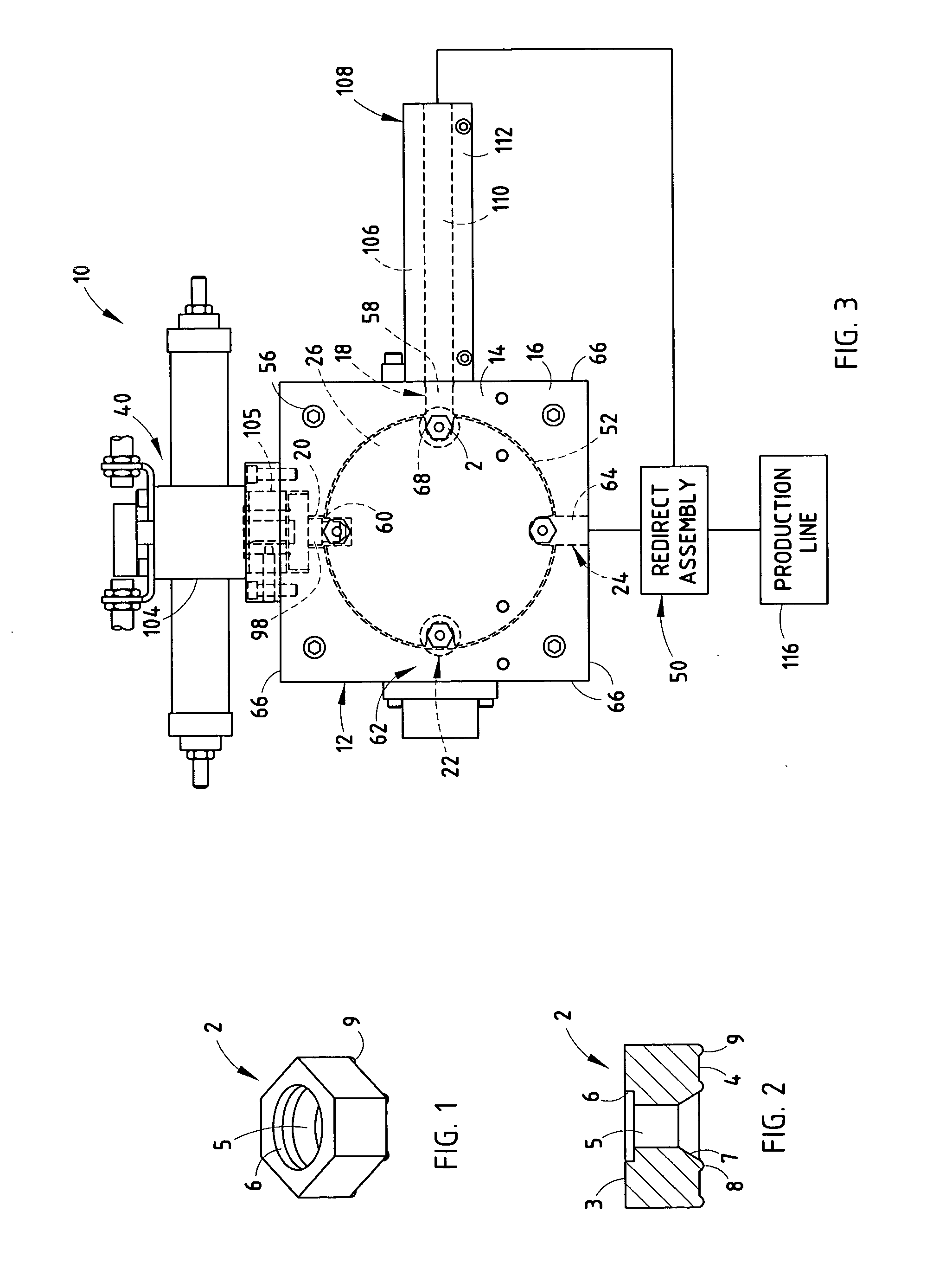
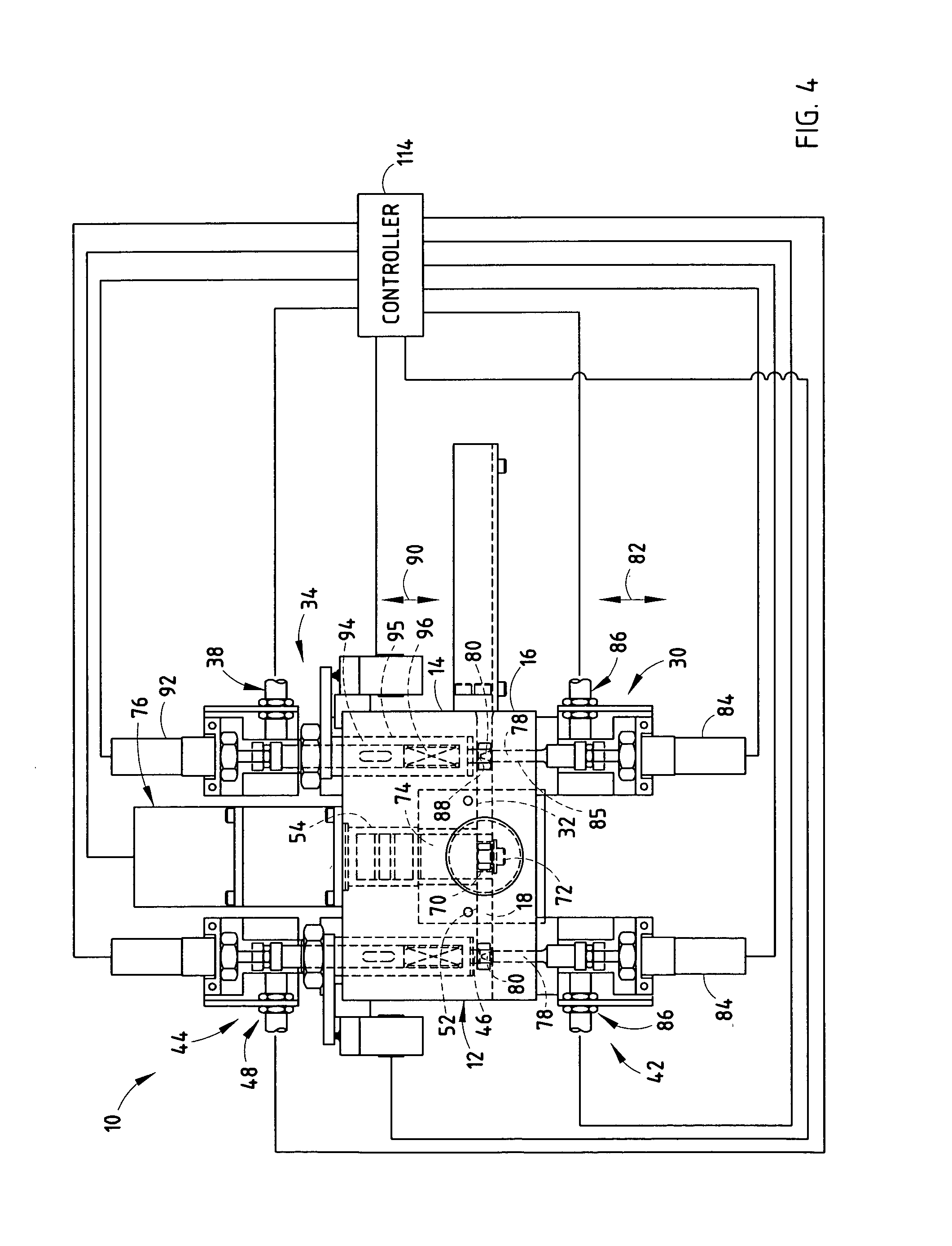
[0017] The reference numeral 10 (FIGS. 3-5) generally designates an escapement assembly embodying the present invention. In the illustrated example, the escapement assembly 10 includes a housing 12 havin...


PUM


Abstract

An escapement system for orienting a plurality of fasteners includes a housing member including a first station and a second station, and a drum member operably coupled with the housing member and adapted to move a fastener from the first station to the second station. The escapement system also includes a first seating assembly adapted to abuttingly engage the fastener at the first station and seat the fastener against the datum surface, wherein a selected one of the housing member and the drum member includes the datum surface. The escapement system further includes a first probe assembly separate from the first seating assembly and including a first probe member adapted to abuttingly engage the fastener and a first proximity switch operably coupled with the first probe, wherein the first proximity switch is configured to indicate proper alignment on the fastener within the first station.

Description

BACKGROUND OF THE INVENTION [0001] This invention relates to a fastener delivery system, and more particularly to an escapement system for properly orienting a plurality of fasteners. [0002] Considerable assembly time can be saved by utilizing automatic delivery of fasteners to manufacturing cells that include automatic welding machines, screw guns, multi spindle machines, and the like. Machines that perform such functions and deliver fasteners are often referred to as “feeder machines.”[0003] Heretofore, feeder machines have typically checked for proper orientation of the fasteners as the fasteners move through the feeder machine by physically probing the fastener. As a specific example, a nut 2 (FIG. 1), adapted to be welded to prefabricated components by an automatic welding machine, are typically probed for proper orientation as the nut 2 enters the feeder machine. More specifically, each nut 2 typically includes a first substantially planar surface 2, a second substantially pla...

Claims


Application Information

Patent Timeline
IPC IPC(8): B23P19/00
CPCB23P19/003B23P19/002
Inventor AMMOND, JOHN E.COGGINS, TIMOTHY P.LANG, PHIL A.
Owner AIRWAY AUTOMATION
Features
  • Generate Ideas
  • Intellectual Property
  • Life Sciences
  • Materials
  • Tech Scout
  • Unparalleled Data Quality
  • Higher Quality Content
  • 60% Fewer Hallucinations
Learn More