Trailing arm suspension with optimized i-beam

a technology of i-beam and suspension, which is applied in the direction of resilient suspension, vehicle spring, vehicle components, etc., can solve the problems of reducing the life of the beam, so as to achieve the effect of reducing weight and cos

Inactive Publication Date: 2005-03-10
THE HOLLAND GROUP
View PDF14 Cites 39 Cited by
  • Summary
  • Abstract
  • Description
  • Claims
  • Application Information

AI Technical Summary

Benefits of technology

[0016] The design approach results in the trailing arm configuration at any section being precisely tailored to the design stress to which the beam will be subjected at that section, reducing the trailing arm material to only that necessary at each section and economizing on weight and cost. Casting the trailing arm, rather than assembling the beam from individual components that are welded together, is the preferred fabrication method as it readily enables the precise beam dimensions determined from the design process to be achieved in the beam as fabricated.

Problems solved by technology

This approach results in sections of the beam having more material than is necessary for the maximum stress imposed on the beam at that section.
This excess material adds to the cost and weight of the beam.
Furthermore, the welds induce stresses into the beam that can contribute to premature failure of the beam.
However, such detailed welding techniques can also increase the cost of fabrication and the weight.
Welded connections can induce in the axle stresses and cracks that can contribute to premature failure of the axle.

Method used


Image

  • Trailing arm suspension with optimized i-beam
  • Trailing arm suspension with optimized i-beam
  • Trailing arm suspension with optimized i-beam

Examples


Embodiment Construction

[0031] For purposes of description herein, the terms “upper,”“lower,”“right,”“left,”“rear,”“front,”“vertical,”“horizontal,” and derivatives thereof shall relate to the invention as oriented in FIGS. 1-3. However, it is to be understood that the invention may assume various alternative orientations and step sequences, except where expressly specified to the contrary. It is also to be understood that the specific devices and processes illustrated in the attached drawings, and described in the following specification are exemplary embodiments of the inventive concepts defined in the appended claims. Hence, specific dimensions and other physical characteristics relating to the embodiments disclosed herein are not to be considered as limiting, unless the claims expressly state otherwise.

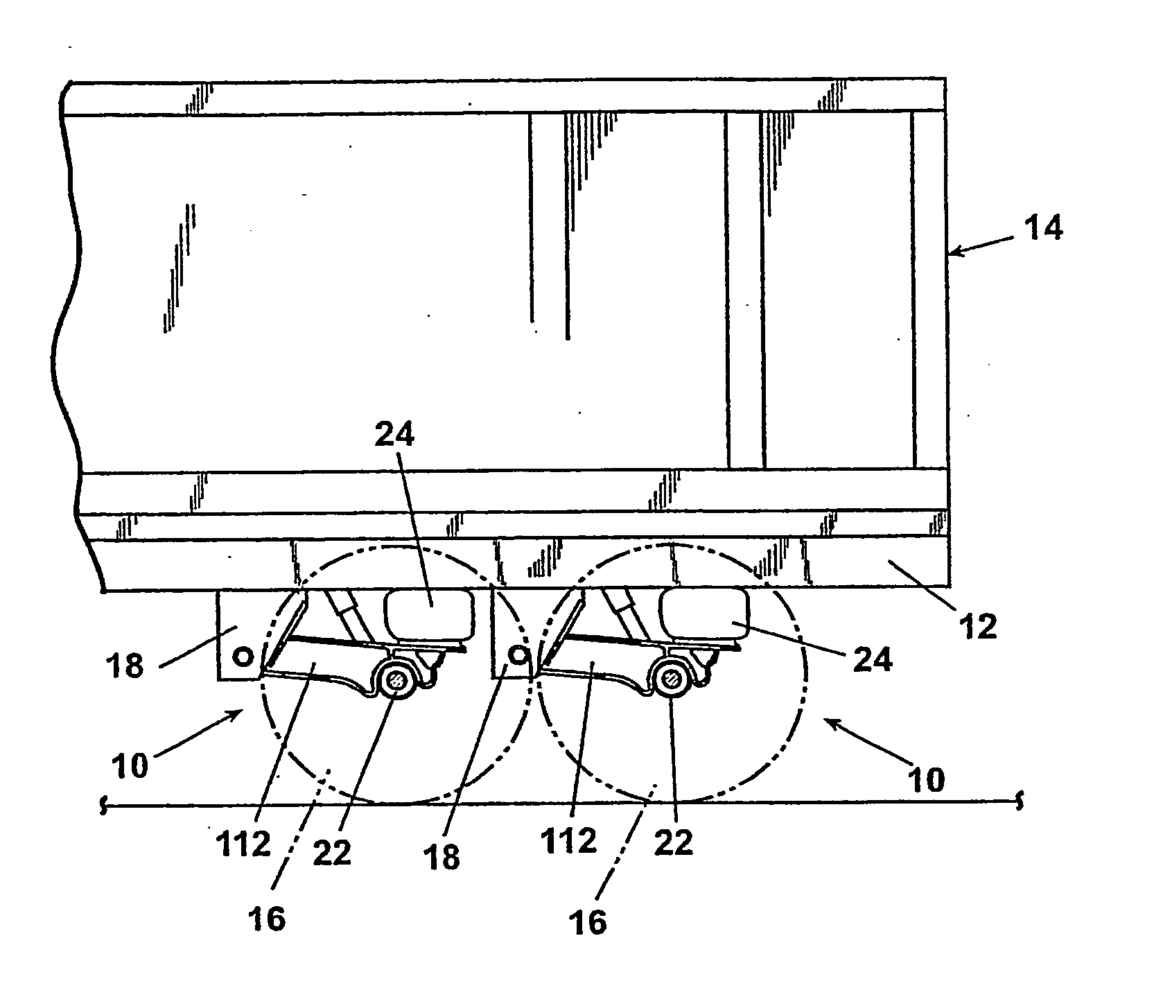
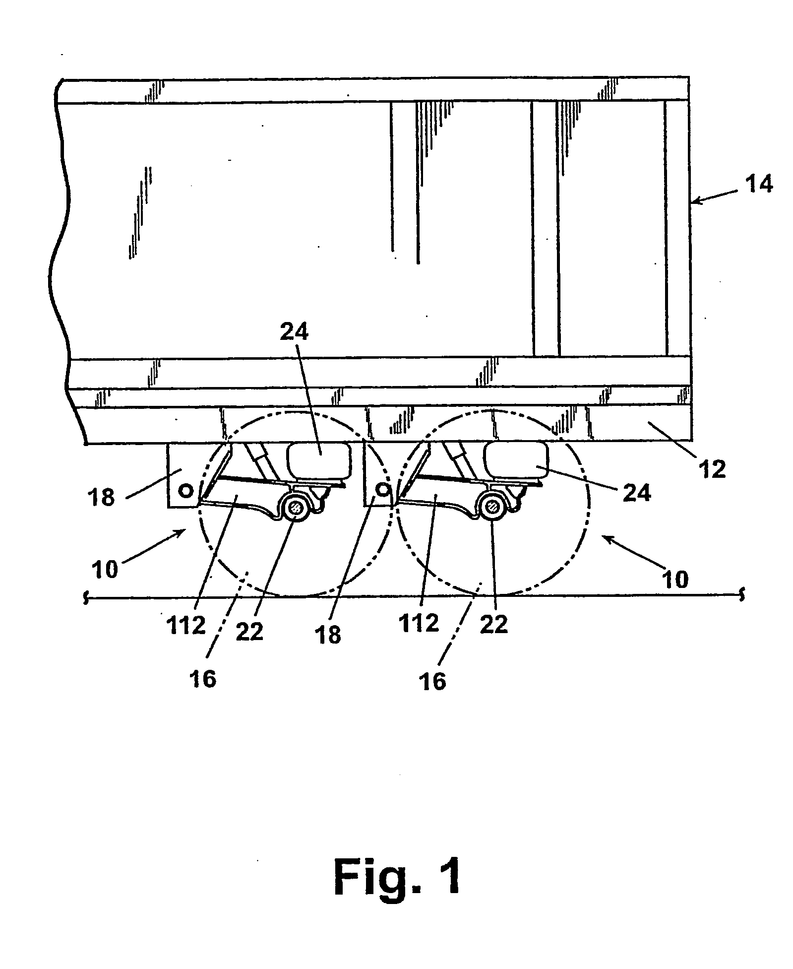
[0032] Referring now to FIG. 1, a trailing arm suspension assembly 10 according to the invention is shown suspended from a trailer frame rail 12 which supports a trailer 14. Two identical suspension asse...


PUM


Abstract

A suspension system includes a pair of trailing arms (112) extending between frame brackets (18) and a wheel-carrying axle (22). Each trailing arm (112) comrises an I-beam portion having a web section and first and second flanges, wherein the thickness of at least one of the flanges vaires along a length thereof. The trailing arms (112) are welded directly to the axle (22).

Description

BACKGROUND OF THE INVENTION [0001] 1. Field of the Invention [0002] The invention relates to vehicle suspension systems, and in particular to suspensions for semi tractor-trails incorporating single-piece, cast trailing arms. [0003] 2. Description of the Related Art [0004] Trailing beam suspensions for semi tractor-trailer combinations are well-known in the trucking industry. The typical trailing beam suspension comprises a hanger bracket suspended from a trailer frame rail. A trailing beam or arm is pivotably connected at one end to the hanger bracket to enable the trailing beam to pivot about a horizontal axis. The pivotable connection may comprise a resiliently bushed connection. The free end of the trailing beam is attached to a spring that is, in turn, attached to the trailer frame rail for cushioning the ride. The spring can comprise a mechanical spring, such as a coil spring, or an air spring. An axle is attached transversely to a pair of trailing beams on either side of the ...

Claims


Application Information

Patent Timeline
Patent Type & Authority Applications(United States)
IPC IPC(8): B60G1/00B60G7/00B60G9/00B60G9/02B60G11/27B60G11/64
CPCB60G7/001B60G7/008B60G9/003B60G11/27B60G11/64B60G2206/8201B60G2202/152B60G2204/148B60G2206/11B60G2206/8101B60G2200/31
Inventor GALAZIN, GREGORY T.DYKSTRA, DANIEL R.
Owner THE HOLLAND GROUP
Why Eureka
Try Eureka