
Packaging plate for magnetic circuit, method for packaging magnetic circuit using the same, and magnetic circuit package

a technology of magnetic circuit and packaging plate, which is applied in the direction of reradiation, magnetic bodies, instruments, etc., can solve the problems of unpredictability of magnetic substances attracted to the magnetic circuit, risk of both equipment and people being endangered, and leakage of magnetic field, so as to reduce the number of packaging steps required, reduce the effect of magnetic attraction and reducing the magnetic field

Inactive Publication Date: 2005-03-10
SHIN ETSU CHEM IND CO LTD
View PDF3 Cites 6 Cited by
  • Summary
  • Abstract
  • Description
  • Claims
  • Application Information

AI Technical Summary

Benefits of technology

The present invention provides a package for a magnetic circuit that reduces the leakage magnetic field and lowers the magnetic attraction acting on the packaging plates, thus reducing the number of packaging work steps. The invention includes a packaging plate with a non-magnetic layer and a magnetic layer, a method for packaging the magnetic circuit using the packaging plate, and a permanent magnet-type magnetic circuit package. The technical effect of the invention is to reduce the need for an iron container and facilitate the packaging process of the magnetic circuit.

Problems solved by technology

On the other hand, it has the disadvantage that magnetic substances may easily penetrate into it from the outside.
However, during transportation of the unit from factory to hospital, in the course of dislocation inside hospital or during a temporary storage etc., magnetic substances can be attracted to the magnetic circuit in unforeseeable ways, because the permanent magnet-type circuit always generates a magnetic field.
Thus, there is the risk that both equipment and people may be endangered by magnetic substances sucked into the magnetic circuit.
When the magnetic circuit is transported by a truck or the like, it has to be first placed in an iron container to reduce the leakage magnetic fields leaking out of the magnetic circuit, thus requiring troublesome handling.
The above-mentioned problem is caused by a leakage magnetic field escaping from the aperture of the magnetic circuit.
However, if a magnetic plate is brought too close to the aperture of the magnetic circuit, an attracting force will be generated due to permanent magnets installed in the magnetic circuit, so that the attaching of the magnetic plate becomes dangerous, and also its dismantling becomes difficult.
But because this alone cannot sufficiently reduce the leakage magnetic field, troublesome transport using an iron container has been required.

Method used


Image

  • Packaging plate for magnetic circuit, method for packaging magnetic circuit using the same, and magnetic circuit package
  • Packaging plate for magnetic circuit, method for packaging magnetic circuit using the same, and magnetic circuit package
  • Packaging plate for magnetic circuit, method for packaging magnetic circuit using the same, and magnetic circuit package

Examples


example

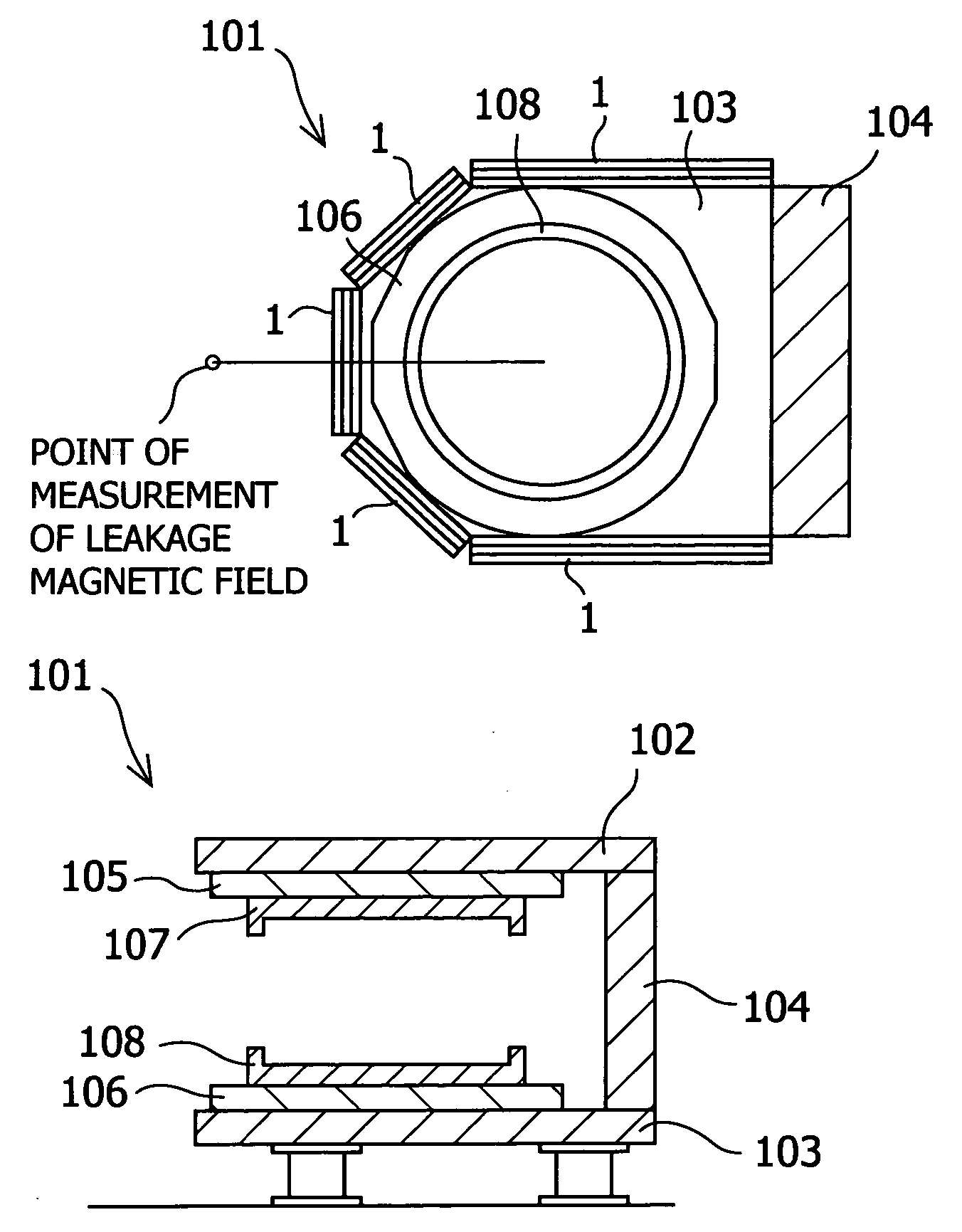
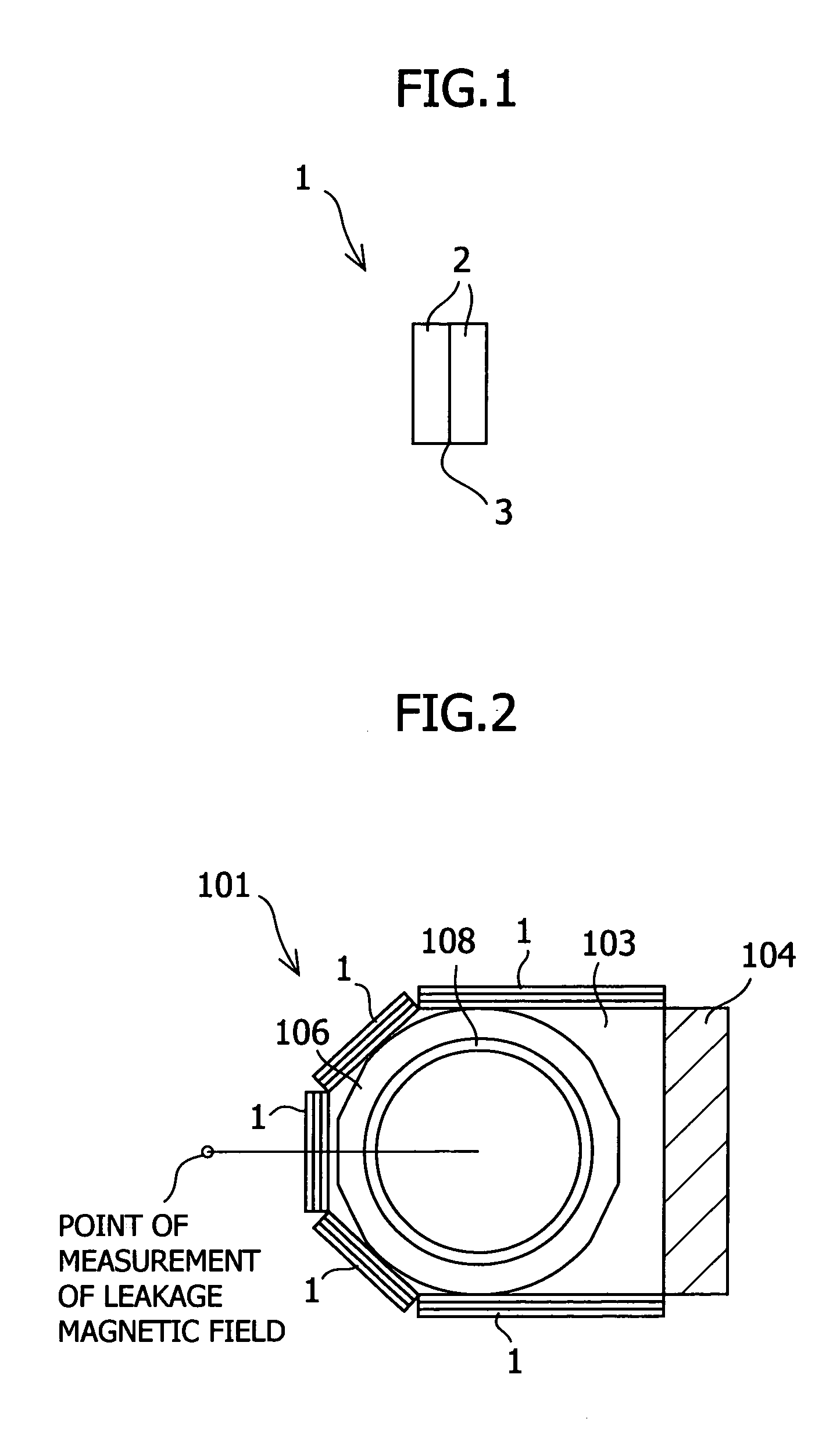
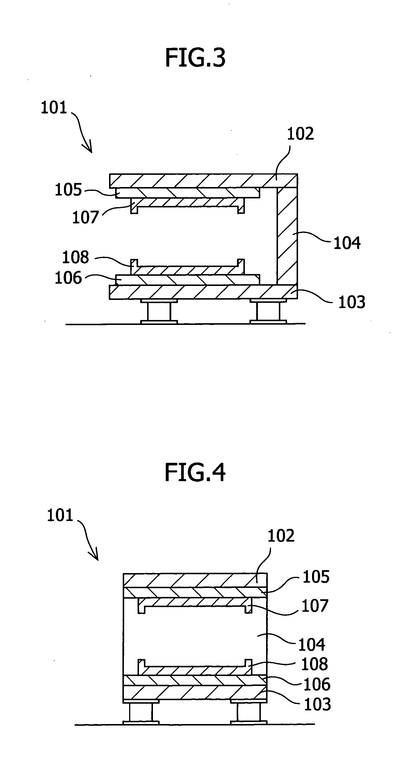
[0027] A working example of the present invention is explained in contrast to a comparative example. However, the scope of the present invention is by no means limited to this example. In the working example, a C-shaped magnetic circuit with a central magnetic field intensity of 0.2 T was used to measure the leakage magnetic field with the gauss meter (FWBELL No.9900) at a point 1 meter away from its center toward the aperture side (see FIG. 2). A packaging plate was fabricated such that a soft iron sheet of 0.3 mm thickness was sandwiched with two sheets of plywood of 10 mm thickness so as to obtain a three-layer structure of non-magnetic / magnetic / non-magnetic layers. As shown in Table 1, a plurality of packaging plates was fitted to the aperture with bolts. FIG. 2 shows the state in which three packaging plates were layered, that is, three magnetic layers and six non-magnetic layers in total.

TABLE 1NumberLeakageof packaging platesmagnetic field (mT)014386490.8

[0028] As becomes c...


PUM

PropertyMeasurementUnit
total thicknessaaaaaaaaaa
magnetic field intensityaaaaaaaaaa

Abstract

It is an object to provide a package for a magnetic circuit, with which a leakage magnetic field escaping from an aperture of a magnetic circuit is reduced and the magnetic attraction acting on the packaging plates is lowered, thus reducing the number of packaging work steps. There are provided a packaging plate for a permanent magnet-type magnetic circuit, the packaging plate comprising at least one non-magnetic layer and at least one magnetic layer; and a method for packaging a permanent magnet-type magnetic circuit, comprising a step of shielding at least a portion of an aperture of a permanent magnet-type magnetic circuit using at least one packaging plates.

Description

BACKGROUND OF THE INVENTION [0001] 1. Field of the Invention [0002] The present invention relates to a packaging plate (as used herein, the term “plate” shall include a “sheet”) for a magnetic circuit and a method for packaging a magnetic circuit using the same. More specifically, the present invention relates to the packaging of a permanent magnet-type magnetic circuit for a magnetic resonance imaging (MRI) system during its transportation and storage. [0003] 2. Description of Related Art [0004] Magnet-type magnetic circuits comprising rare earth magnets has been mainly used for magnetic circuits comprising permanent magnets for magnetic resonance imaging systems. Such magnet-type magnetic circuits comprise magnets, yokes through which the magnetic flux from the magnets passes, and pole pieces that are ordinarily arranged on the magnet surface and made of a soft magnetic substance such as soft iron to generate a homogenous magnetic field in the gap between the magnets. [0005] Refer...

Claims


Application Information

Patent Timeline
Patent Type & Authority Applications(United States)
IPC IPC(8): G01R33/383H01F7/02
CPCH01F7/0205G01R33/383
Inventor DOI, YUHITO
Owner SHIN ETSU CHEM IND CO LTD
Learn More