Vibration absorbing devices for fuel pumps

a technology of vibration absorption device and fuel pump, which is applied in the direction of positive displacement liquid engine, piston pump, electric control, etc., can solve the problem that the joint portion 102 held in a straddling manner may not effectively reduce the vibration produced by the fuel pump, and achieve the effect of further effective reduction of the vibration of the fuel pump

Inactive Publication Date: 2005-03-10
AISAN IND CO LTD
View PDF4 Cites 12 Cited by
  • Summary
  • Abstract
  • Description
  • Claims
  • Application Information

AI Technical Summary

Benefits of technology

[0017] In another aspect of the present teachings, the vibration absorbing device further includes an adapter connecting the fuel tank to the second member. The adapter is made of a resilient member, so that the second member resiliently supports the fuel tank. Therefore, the vibration of the fuel pump can be further effectively reduced.

Problems solved by technology

As a result, the joint portions 102 held in a straddling manner may not effectively reduce the vibrations produced by the fuel pump 104.

Method used


Image

  • Vibration absorbing devices for fuel pumps
  • Vibration absorbing devices for fuel pumps
  • Vibration absorbing devices for fuel pumps

Examples


first representative embodiment

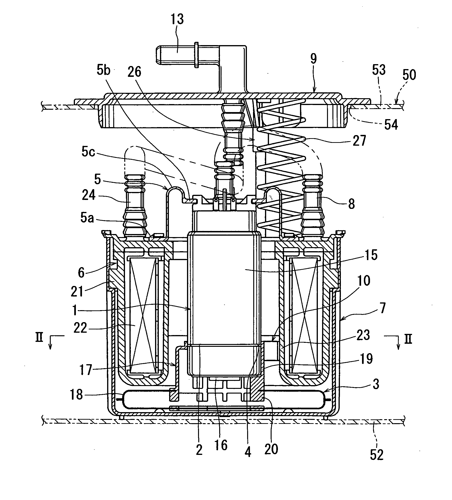
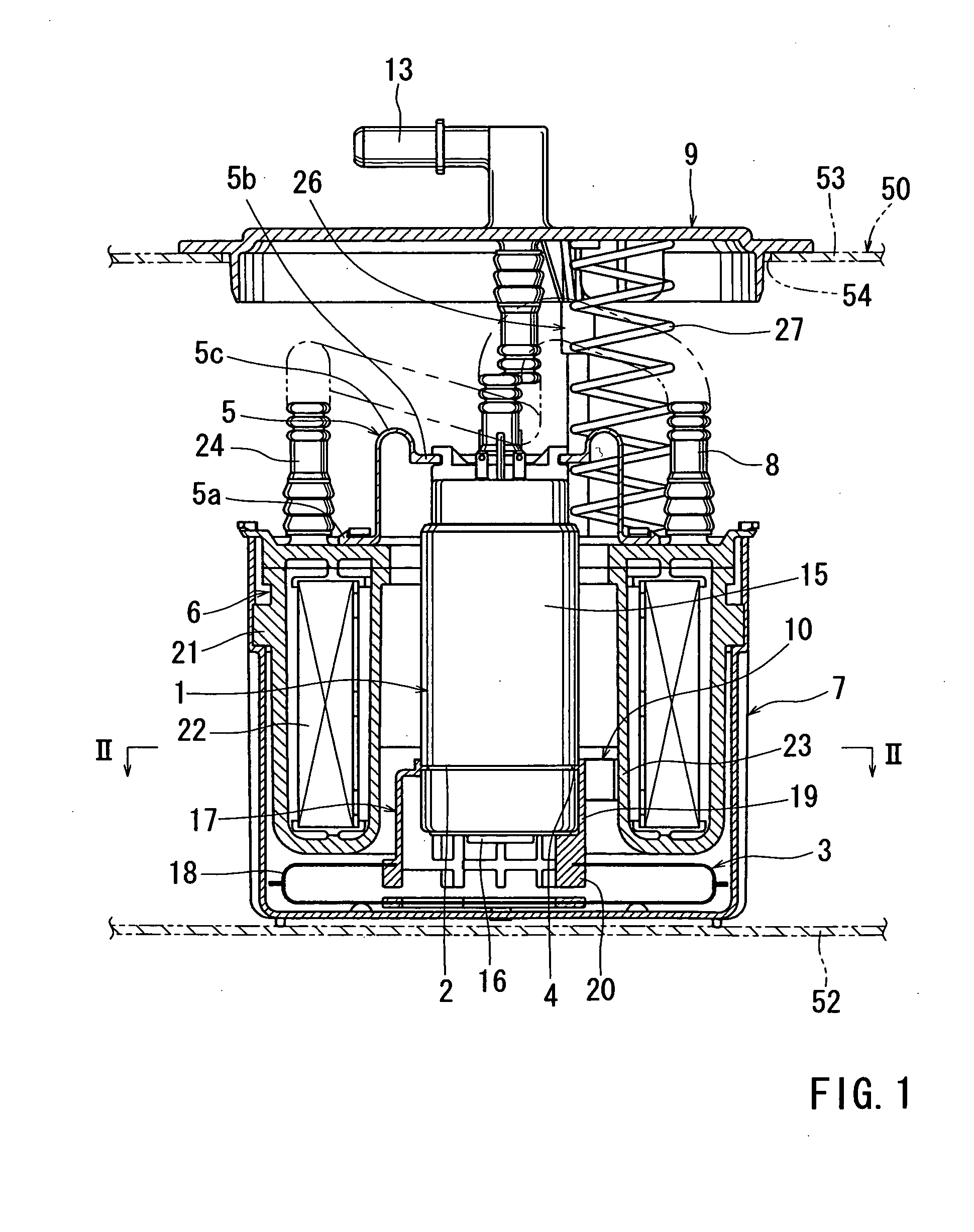
[0031] First Representative Embodiment

[0032] Referring to FIGS. 1 and 2, a first representative device for absorbing vibrations produced by a fuel pump is shown. The first representative device is applied to a fuel delivery system that is configured as a module including a fuel filter, a reservoir cup, and a flange, etc. Therefore, the fuel delivery system will be first described and thereafter the first representative device will be described. The fuel delivery system is assembled within a fuel tank 50. The fuel tank 50 defines a substantially sealed space for storing fuel. The fuel tank 50 has a bottom plate 52, a top plate 53, and a sidewall (not shown). An opening 54 is formed in the top plate 53.

[0033] As shown in FIG. 1, the fuel delivery system includes a fuel pump 1, a fuel filter 6, a reservoir cup 7, and a flange 9. For convenience of explanation, these elements will be described in the order of the reservoir cup 7, the flange 9, the fuel pump 1, and the fuel filter 6.

[0...

second representative embodiment

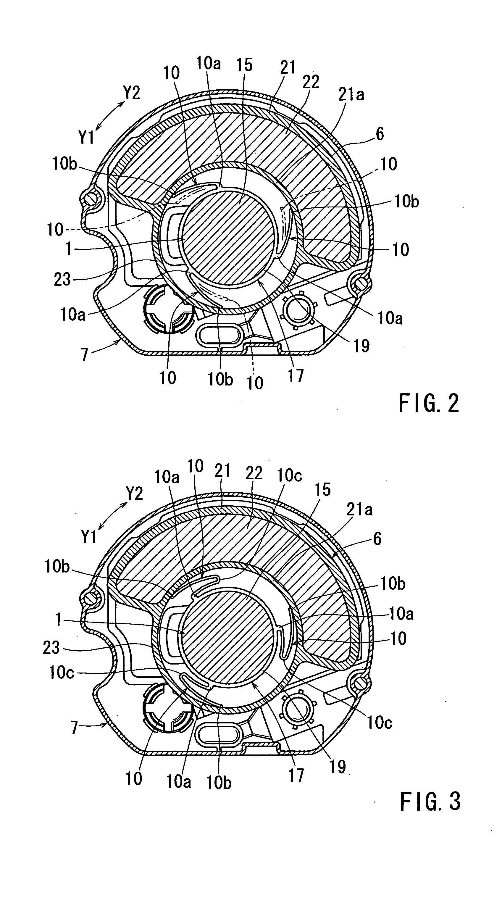
[0060] Second Representative Embodiment

[0061] As shown in FIG. 3, according to the second representative embodiment, each of the vibration absorbing portions 10 has a substantially U-shaped bent part 10c that is turned back upon itself at substantially the middle position between the base first end 10a and the free second end 10b. Therefore, the vibration absorbing portions 10 are able to deform in the radial direction of the armature of the fuel pump 1. As a result, the vibration absorbing portions 10 can effectively reduce the vibrations of the fuel pump 1 in the radial direction of the armature.

third representative embodiment

[0062] Third Representative Embodiment

[0063] As shown in FIG. 4, the fuel delivery system according to the third representative embodiment does not include the reservoir cup 7 that is provided in the first representative embodiment. In this connection, the filter case 21 of the fuel filter 6 and the flange 9 are connected to one another in a different manner than the first representative embodiment. The joint device 26, the spring 27, and the second pipe 24, are omitted in the third representative embodiment.

[0064] As shown in FIG. 4, an outer sleeve 28 is formed integrally with the filter case 21 and extends vertically upward from the upper end of the outer periphery of the filter case 21. On the other hand, an inner sleeve 30 is formed integrally with the flange 9 and extends vertically downward from the lower surface of the flange 9 so as to be fitted into the outer sleeve 28. A suitable number of engaging holes 29 are formed in the upper portion of the outer sleeve 28 in order ...


PUM


Abstract

A vibration absorbing device is disposed between a fuel tank and a fuel pump of a fuel delivery system. The vibration absorbing device includes a first member fixed in position relative to the fuel pump, a second member fixed in position relative to the fuel tank, and a plurality of vibration absorbing members. The vibration absorbing members are provided on one of the first and second members and resiliently slidably contact with the other of the first and second members.

Description

[0001] With this type of recent arrangement, opposite ends of each joint portion 102 are respectively connected to the filter case 100 and the annular portion 101, so that each joint portion 102 is held to extend between the filter case 100 and the annular portion 101 in a straddling manner. However, with this type of arrangement, vibrations that may be produced during the operation of the fuel pump 104 may be readily transmitted to the fuel tank via the annular portion 101, the joint portions 102, and the filter case 100. [0002] In addition, the joint portions 102 extend from the annular portion 101 to the filter case 100 in a direction opposite to the rotational direction (indicated by an arrow Y in FIG. 11) of the armature of the motor of the fuel pump 104. Therefore, the inertial force produced by rotation of the armature may apply thrust to the joint portions 102. As a result, the joint portions 102 held in a straddling manner may not effectively reduce the vibrations produced ...

Claims


Application Information

Patent Timeline
Patent Type & Authority Applications(United States)
IPC IPC(8): F02M37/10F16F15/04
CPCF16F15/04F02M37/106
Inventor SUZUKI, NOBUOHARA, TETSUYA
Owner AISAN IND CO LTD
Why Eureka
Try Eureka