Three stage low NOx burner and method

a burner and nitrogen oxide technology, applied in the field of air staged low nitrogen oxide burners, can solve the problems of difficult to predict factors, increase in no/sub>x/sub>emissions, and substantial added capital expense of piping and controlling the recirculation flue gas, so as to reduce the emissions of co and hcs, and reduce the energy output. , the effect of low nox emissions

Active Publication Date: 2005-03-10
HAUKE MFG
View PDF41 Cites 20 Cited by
  • Summary
  • Abstract
  • Description
  • Claims
  • Application Information

AI Technical Summary

Benefits of technology

[0025] An advantage of the present invention is that it provides a gas burner capable of very low NOx emissions when fired with either ambient or preheated combustion air.
[0026] Another advantage of the present invention is that it reduces emissions of CO and HCs during cold furnace startups.
[0027] Another advantage of the present invention is that it is capable of a significant reduction in energy output, known as high turndown, while maintaining low excess air at or near stioichiometric operation.
[0028] Another advantage of the present invention is that a portion of the flame is visible and stable under all firing conditions, which promotes flame safety.
[0029] Another advantage is that many of the elements of the present invention are refractory and are capable of withstanding very high air preheat and furnace temperatures.
[0030] A further advantage of the present invention is that it easier to maintain, install, and operate as only a single fuel and a single air inlet connection to the burner is required.

Problems solved by technology

A well-known problem in the industry for many years with the use of conventional burner designs utilizing preheated combustion air is higher flame temperatures which in turn contribute to an exponential increase in NOx emissions.
However, these factors are difficult to predict because burners for different industrial processes must operate at various furnace chamber temperatures, have various oxygen concentrations in the work chambers, may or may not have preheated combustion air, and are required to operate at different heat inputs depending on changing heat load requirements.
However, the added capital expense for piping and controlling the recirculated flue gases are substantial.
WO 01 / 35022 A1, for lower NOx emissions but does not address the cold furnace startup issue.
However, this design requires a separate ambient air connection to the burner body for flame stabilization and complete fuel burnout during cold furnace startups and / or below the auto ignition temperature of the fuel gas, again adding maintenance, installation, and operation costs.

Method used


Image

  • Three stage low NOx burner and method
  • Three stage low NOx burner and method
  • Three stage low NOx burner and method

Examples


Embodiment Construction

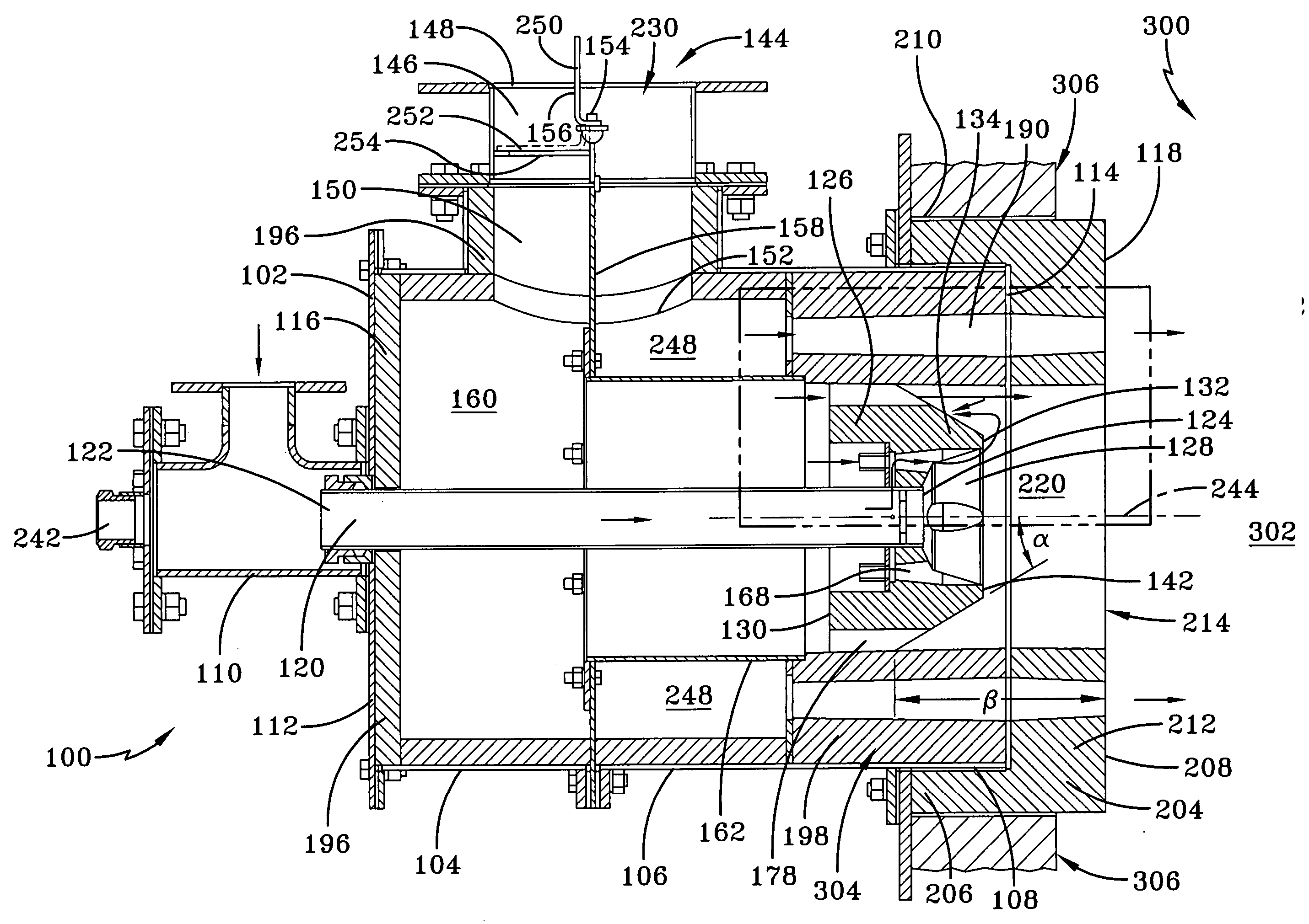
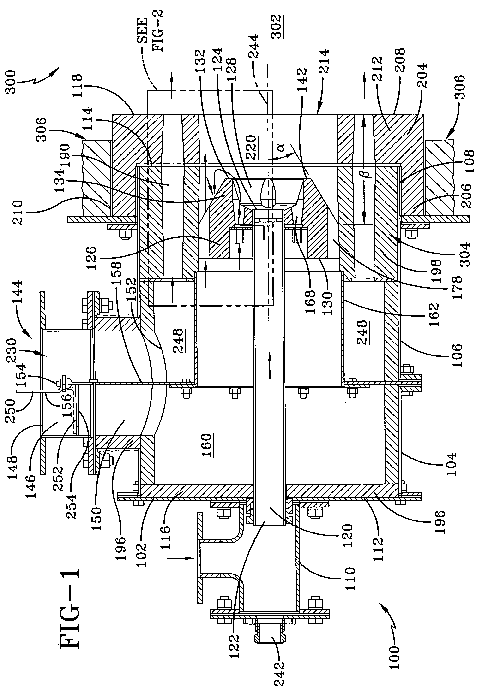
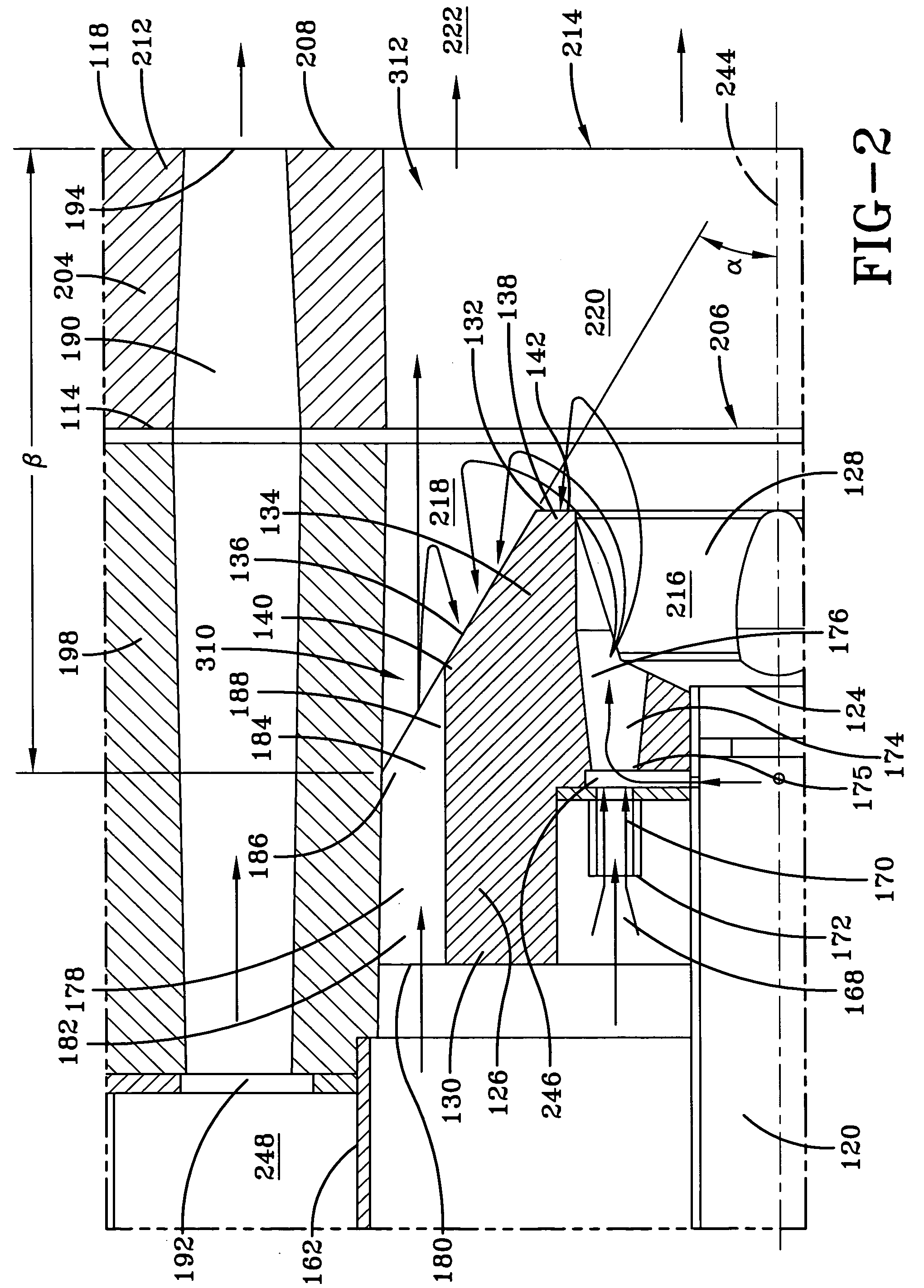
[0043]FIG. 1, FIG. 2, FIG. 8, FIG. 9, and FIG. 10 depict a cross-section of an embodiment of the burner 100 of the present invention. The burner 100 of the present invention has a main burner body 102, which contains most of the elements of burner 100. A main burner body shell 104 encapsulates the main burner body 102. The main burner body shell 104 preferably comprises a material selected from the group consisting of carbon steel, stainless steel, and combinations thereof, although any metal or high temperature metal alloy may be used for the main burner body shell 104. The burner 100 extends into the interior 302 of the furnace 300 through an aperture 304 in the furnace wall 306. The burner 100 comprises two main elements, the main burner body 102 and the interior section 204, which is mounted within the furnace wall 306. The interior portion 108 of the main burner body is nested within the interior section 204.

[0044] The burner 100 has an upstream end 116 and a downstream end 11...


PUM


Abstract

The present invention is an air-staged low NOx burner for firing a gaseous fuel. The burner fires three stages, with the first stage of combustion taking place substantially within a burner cup section of a refractory baffle, the second stage of combustion taking place adjacent to the baffle and downstream of the baffle, and the third stage of combustion within a furnace. The flow of main combustion air adjacent to the baffle creates a negative pressure zone adjacent to the baffle. The present invention is also a method for low NOx staged combustion.

Description

CROSS-REFERENCE TO RELATED APPLICATIONS [0001] This application claims the benefit of U.S. Provisional Application No. 60 / 500,599, filed Sep. 5, 2004, which application is incorporated herein by reference.FIELD OF THE INVENTION [0002] The present invention is generally directed to an air staged low nitrogen oxide burner. BACKGROUND OF THE INVENTION [0003] One of the by-products created by the combustion of hydrocarbon (HC) fuels in burners that use atmospheric air is nitrogen oxide (NOx). A well-known problem in the industry for many years with the use of conventional burner designs utilizing preheated combustion air is higher flame temperatures which in turn contribute to an exponential increase in NOx emissions. Efforts to save fuel and increase combustion efficiency via recuperative and / or regenerative combustion systems combined with stricter governmental permitting laws for acceptable NOx emissions from furnaces has led to a much greater awareness and need to solve this problem...

Claims


Application Information

Patent Timeline
Patent Type & Authority Applications(United States)
IPC IPC(8): F23C6/04F23D14/12F23D14/70
CPCF23C6/045F23C2201/20F23D14/70F23D14/125F23C2202/40
Inventor FEESE, JAMES J.WARTLUFT, BRUCE A.
Owner HAUKE MFG
Why Eureka
Try Eureka