Orthopaedic surgery planning

a technology for orthopaedic surgery and planning, applied in the field of orthopaedic surgery planning, can solve the problems of inability to accurately account for and correct achieve the effect of reducing the direct cost of films and indirect costs, accurately taking into account and correcting, and increasing the chance of operation success

Active Publication Date: 2005-03-10
MERIDIAN TECH LTD
View PDF14 Cites 78 Cited by
  • Summary
  • Abstract
  • Description
  • Claims
  • Application Information

AI Technical Summary

Benefits of technology

[0013] allowing a user to reconfigure the geometrical construct by adjusting the geometric parameters according to the anatomical features of the underlying patient image; and
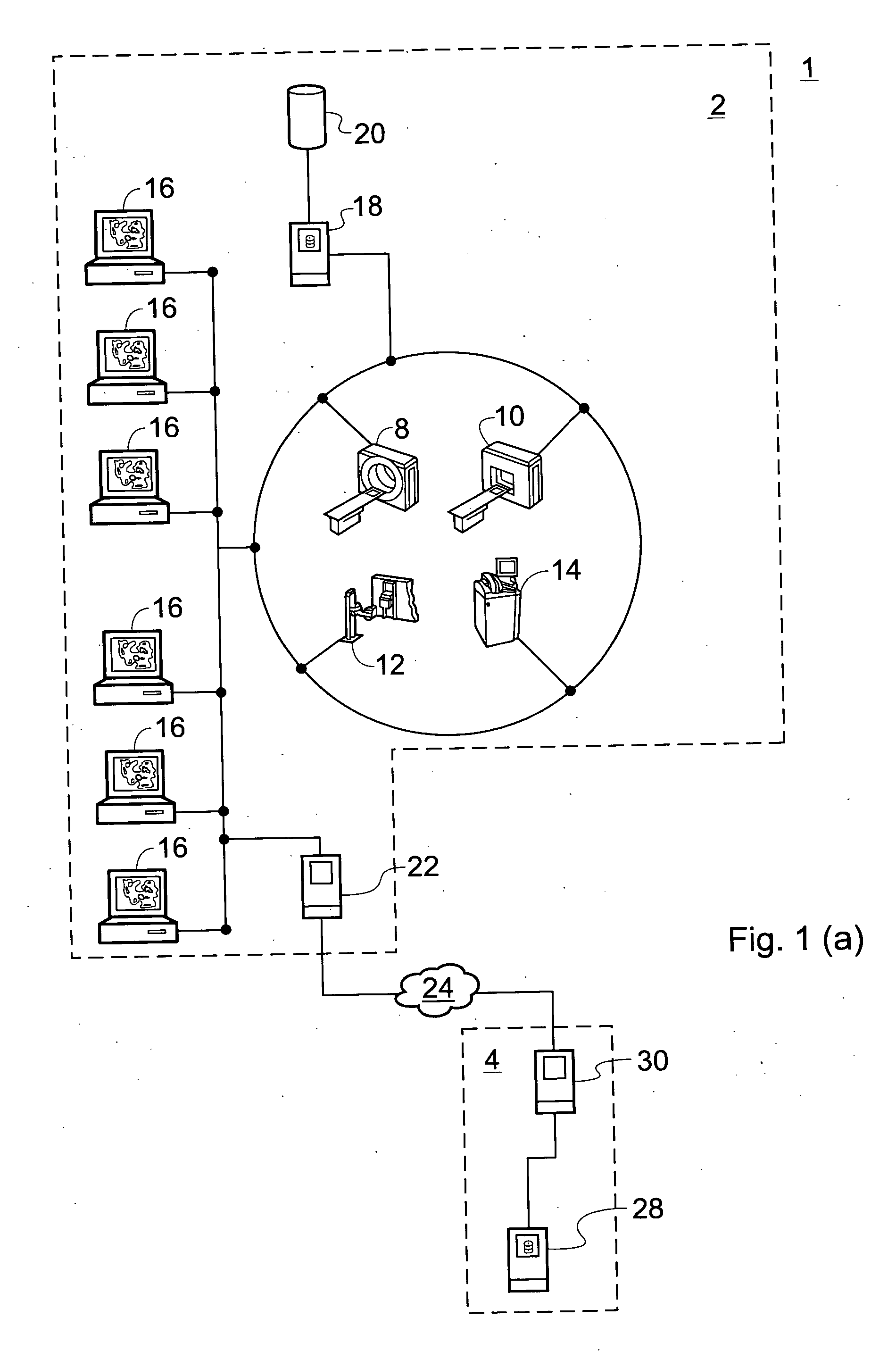
[0073] In a preferred embodiment, the library of templates is stored such that it can be accessed by the processor via the Internet. This arrangement gives a central library that can be administered by a single provider and accessed by users in any hospital with Internet access. In this way, library can conveniently be kept fully up to date for all users.

Problems solved by technology

Such features are advantageous over corresponding ways of working with conventional images such as X-ray films, which exist only as a single version; are costly to produce, time-consuming to transfer, for example via internal and external postal networks; and are prone to loss or damage.
This is costly, slow and negates many of the advantages of the digital image systems.

Method used


Image

  • Orthopaedic surgery planning
  • Orthopaedic surgery planning
  • Orthopaedic surgery planning

Examples


first embodiment

[0088] Hip Replacement Surgery Planning

[0089] The first embodiment of the invention relates to computer-implemented planning for hip replacement surgery. In this operation, the head of the femur is replaced with a metal implant having a stem which is inserted into the canal within the femur (femoral component), and / or the acetabulum in the pelvis is replaced with a metal, ceramic or plastic cup-shaped implant (acetabular component). In this example, the planning is based on a previously obtained X-ray image of a patient's pelvic region, although images obtained by alternative imaging techniques may also be used.

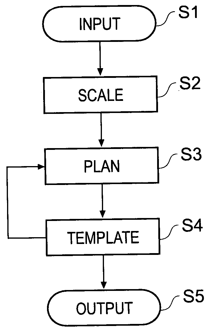
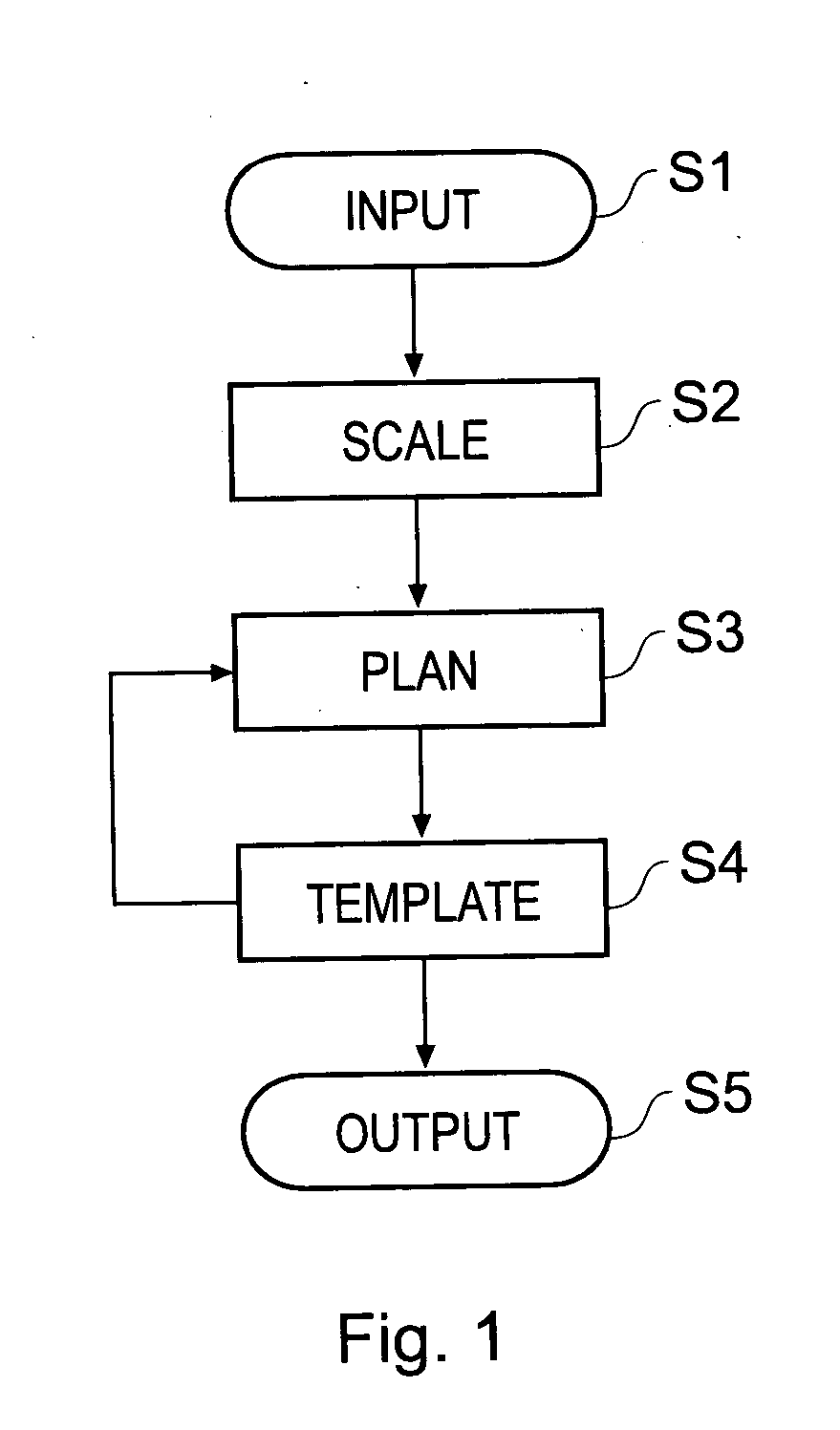
[0090]FIG. 1 shows the basic steps of the planning procedure.

[0091] In Step S1, an input step, an X-ray image is loaded into a computer system and displayed to a user. The computer system contains software operable to execute the various steps of the planning procedure. The X-ray image is an anterior-posterior (from the front) view of the patient showing anatomical features...

second embodiment

[0138] Knee Replacement Surgery Planning

[0139] The second embodiment of the invention relates to computer-implemented planning for knee replacement surgery. In such surgery, the knee capsule is opened, and the ends of the femur and tibia are trimmed and augmented with implants which may or may not be held in place with cement. The femoral component is a metal shell, and the tibial component is a metal and plastic trough.

[0140] This embodiment has the same basic steps as the first embodiment, and the planning procedure is performed in a similar way. The two embodiments differ in that the knee replacement planning is usually based on two previously obtained X-ray images of a patient's knee, one from the side (medio-lateral (ML) view) and one from the front (anterior-posterior (AP) view). Unlike the hip, where enough information can usually be derived from a single AP X-ray image, two different views of the knee are used to ensure that the selected prosthesis is a sufficiently good fi...


PUM


Abstract

A computer-implemented method of planning orthopaedic surgery comprises providing a library of templates representing orthopaedic prostheses, displaying and scaling one or more patient images such as X-ray images, allowing a user to reconfigure geometrical constructs displayed over the images to match the construct to anatomical features shown in the image; and selecting one or more templates from the library in accordance with parameters of the reconfigured constructs. The templates correspond to the orthopaedic prosthesis or prostheses which are most suitable for the patient. Hip replacement surgery can be planned using a single patient image. Knee surgery can be planned using two patient images showing different views of the anatomical features, in which case geometrical constructs for use with each view are provided. The library of templates is accessible via the Internet so as to be accessible by users in any location and readily updateable.

Description

RELATED APPLICATION [0001] This application claims priority from United Kingdom Patent Application Number 0222414.5, filed Sep. 26, 2002, which is hereby incorporated by reference in its entirety. TECHNICAL FIELD [0002] The disclosed embodiments relate to methods and computer program products for planning orthopaedic surgery, in particular surgery for the replacement of hip and knee joints. BACKGROUND OF THE INVENTION [0003] Orthopaedic surgery includes the replacement of damaged or worn joints with prostheses or implants. It is desirable to perform some pre-operative planning in order to select a prosthesis which is an appropriate size for the patient. Typically, this is done by using templates representing a two-dimensional projection of a three-dimensional prosthesis. The templates are in the form of pre-printed acetate sheets which are overlaid on X-ray images of the joint which is to be replaced. This technique allows a surgeon to choose a suitable prosthesis from those availab...

Claims


Application Information

Patent Timeline
Patent Type & Authority Applications(United States)
IPC IPC(8): A61B17/15A61B19/00A61F2/00A61F2/30A61F2/32A61F2/34A61F2/36A61F2/38G16H20/40G16H30/40G16H40/67G16H70/20
CPCA61B17/15G06F19/3437A61B19/50A61B19/52A61B2019/5238A61B2019/5289A61F2/30942A61F2/32A61F2/34A61F2/36A61F2/367A61F2/38A61F2/3859A61F2/389A61F2002/3008A61F2002/30616A61F2002/30948A61F2002/30953A61F2002/30963A61F2002/3611A61F2250/0098A61F2310/00011A61F2310/00179G06F19/321G06F19/324G06F19/3418A61B17/154A61B90/36A61B2090/364A61B2090/376A61B34/10G16H50/50G16H40/67G16H20/40G16H70/20G16H30/40
Inventor KITSON, DAVID
Owner MERIDIAN TECH LTD
Why Eureka
Try Eureka