
Variations of biopsy jaw and clevis and method of manufacture

a technology of jaw and clevis, which is applied in the field of endoscopic instruments, can solve the problems of high cost and time consumption of parts and assembly, and achieve the effects of less parts, increased efficiency, and more efficient design

Inactive Publication Date: 2005-03-10
KRZYZANOWSKI JACEK
View PDF9 Cites 1212 Cited by
  • Summary
  • Abstract
  • Description
  • Claims
  • Application Information

AI Technical Summary

Benefits of technology

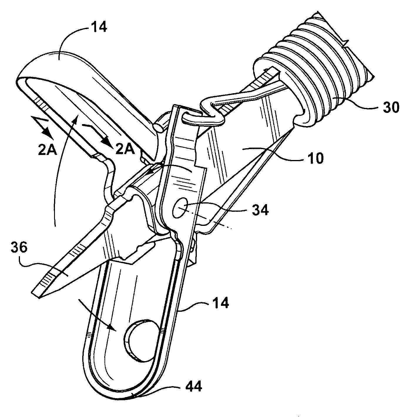
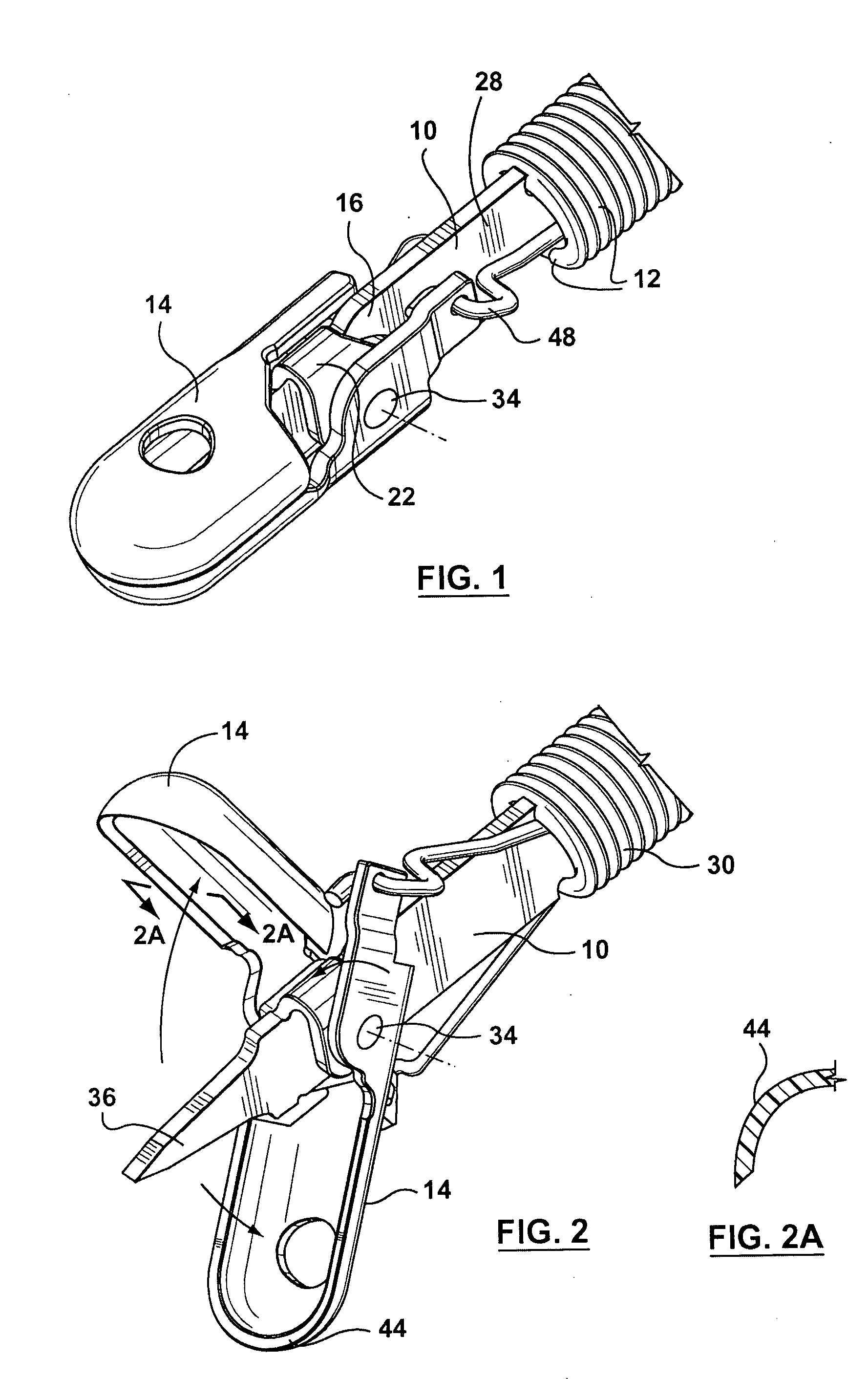
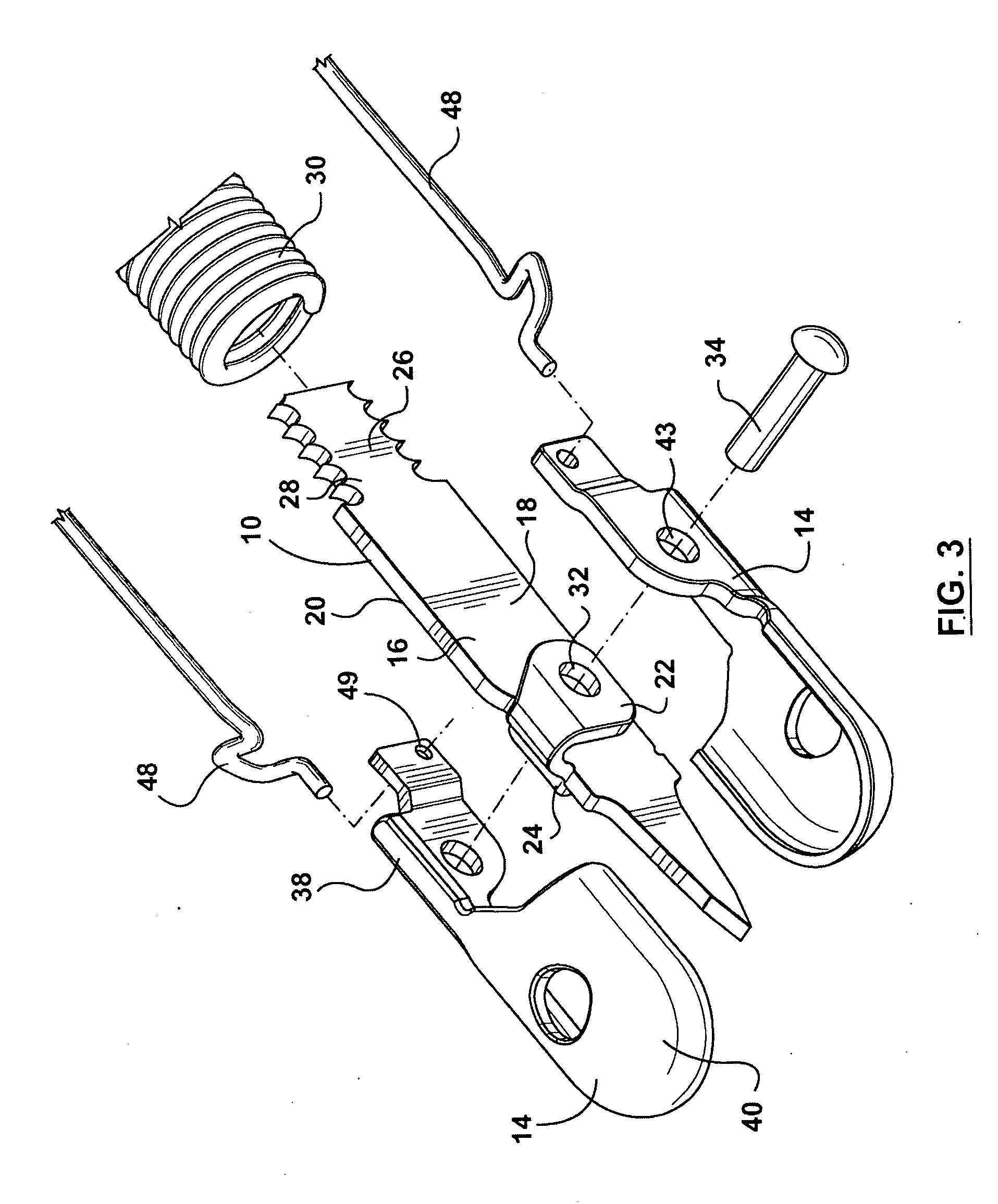
[0013] Advantages of the present invention are: less parts, more efficient design, coined cutting edge makes for a harder edge, coined exposed edges deburred early on during manufacture for increased efficiency, progressive stamping method efficient, less overall costs, flap arrangement on clevis itself for increased efficiency when assembling; chamfered edges early on in method of manufacture to improve production with less chance of device catching within the endoscope channel.

Problems solved by technology

The majority of these devices are complex, extremely small and delicate so that the manufacture of parts and assembly requires precision and is costly and time consuming.
Prior art biopsy jaws have been developed to address some of the aforenoted problems, however these devices and methods to do not disclose a simplified device that includes an improved cutting edge, is inexpensive to manufacture and is efficient to assemble.

Method used


Image

  • Variations of biopsy jaw and clevis and method of manufacture
  • Variations of biopsy jaw and clevis and method of manufacture
  • Variations of biopsy jaw and clevis and method of manufacture

Examples


first embodiment

[0046] At least one pivot hole 72 may be located through the molded portions 62 and 64 respectively and the central portion 56 of the cleivs 50. The pivot hole 72 can receive a pivot pin 74 so as to mount the pair biopsy cups 52 to the clevis 50. The clevis 50 may have a distal end 76 that is pointed or the distal end 76 may be blunt. The biopsy cups 54 may be configured as described above for the

[0047] Referring to FIGS. 8 and 9, there is illustrated in perspective and exploded views, a clevis 78 for a biopsy jaw assembly 80 having a pair of biopsy cups 82 in accordance with a third preferred embodiment of the present invention. The clevis 78 includes a central portion 84 having a first side 86 and a second side 88. At least two spacers 90 and 92 respectively, are positioned so that one spacer 90 is positioned on the first side 86 and a second spacer 92 is positioned on the second side 88.

[0048] A mounting portion 94 may be connected to the central portion 84. The mounting portion...

fourth embodiment

[0050] Referring to FIGS. 10 and 10A there is illustrated in perspective views, a biopsy jaw cup 106 in accordance with the present invention. The biopsy cup 106 may have a jaw cup 108 with a distal end 110 and a proximal end 112 and exposed edges 113 that have been chamfered. The chamfering of the exposed edges 113 eliminates any rough edges that may damage the channel of the endoscope. The distal end 110 may have a chamfered, coined cutting edge 114, while the proximal end 112 may have at least one arm 116. The arm 116 may further comprise a flap 118 that is adapted to receive a clevis 120. The flap 118 may further include a pivot hole 122 for mounting the biopsy cup 106 to the clevis 120. The arm 116 may also have a pivot hole 122.

[0051] Referring to FIGS. 10B, 11, and 11A there is illustrated in perspective and cross-sectional views, the biopsy cup 106 assembled into a biopsy jaw assembly 124. FIGS. 11 and 11A illustrate the biopsy cup 116 with a pivot pin 126 mounted through th...


PUM


Abstract

A clevis for a biopsy jaw assembly having a pair of biopsy cups, which includes a central portion having a first side and a second side. At least two flaps are oppositely folded to one another with one flap on the first side and one flap on the second side. A mounting portion may be connected to the central portion. The mounting portion may have a proximal end for mounting on an actuator for positioning the biopsy jaw assembly.

Description

FIELD OF THE INVENTION [0001] This invention relates in general to endoscopic instruments and more particularly to variations of a biopsy jaw and clevis and method of manufacturing same in a more cost efficient manner to produce a superior product. BACKGROUND OF THE INVENTION [0002] There are numerous biopsy jaw devices available that are primarily used in the endoscopy field in the removal of tissues from inside the body. The majority of these devices are complex, extremely small and delicate so that the manufacture of parts and assembly requires precision and is costly and time consuming. [0003] Prior art biopsy jaws have been developed to address some of the aforenoted problems, however these devices and methods to do not disclose a simplified device that includes an improved cutting edge, is inexpensive to manufacture and is efficient to assemble. For example, U.S. Pat. No. 6,514,269 issued on Feb. 4, 2003 to Yamamoto and relates to an endoscopic treatment instrument that has cu...

Claims


Application Information

Patent Timeline
IPC IPC(8): A61B10/00A61B10/06A61B17/28A61B17/32
CPCA61B10/06A61B2017/320064A61B2017/294A61B2017/2939
Inventor KRZYZANOWSKI, JACEK
Owner KRZYZANOWSKI JACEK
Learn More