Rotational method and apparatus for welding beam-mount structure to the side(s) of a column

a beam-mount structure and rotating method technology, applied in the direction of rod connections, joists, branching pipes, etc., can solve the problems of deformation, difficult to correct or manage, and difficult to solve the culpri

Active Publication Date: 2005-03-17
CONXTECH INC
View PDF17 Cites 29 Cited by
  • Summary
  • Abstract
  • Description
  • Claims
  • Application Information

AI Technical Summary

Benefits of technology

[0003] For a number of important reasons which include, among other things, a desire for large strength-to-weight ratios in columns, tubular steel columns are highly desirable for use in plural-story buildings. Especially long, unitary columns are also desirable in that they can greatly reduce building-frame assembly time by minimizing the number of column-to-column (stack) connections that are necessary to achieve full building-frame height. Such columns, however, can present challenges during manufacture, and later during assembly with beams, regarding which (in both cases) there are manufacturing and assembling steps wherein it is conventional that high heat (due to welding operations) is (or may be) involved. Such heat can prove to be a difficult culprit (a) during manufacture where a column can warp or twist (even slightly) during cool-down, and (b) during building-frame assembly where extreme local hot regions created during welding operations can introduce similar undesirable, and often difficult to correct or manage, deformations.
[0005] The desirability of employing hollow tubular columns in a building frame structure has thus been outlined generally above for background reasons, and as will now be seen, the present invention, methodology and structure, involve a unique method, and an apparatus which implements that method, for deploying and weld-attaching beam mounts in clusters which are appropriately distributed along the length of, and on the outside surfaces, or sides, of such a column. Such deployed and attached beam mounts ultimately provide attaching (anchoring) locations for the ends of beams equipped with a beam-end attaching component, such as those mentioned above, and generally illustrated in FIG. 1. Very specifically, the present invention offers a unique methodology and apparatus which enable precision, and non-heat-deforming, deploying and attaching of clusters of such beam mounts to the outer sides in such a column. As will be seen, the method and apparatus of the present invention are employable completely, and advantageously, in an off-site manner, and under precision control, including computer and robotic control if desired, so as to prepare columns for delivery to a building site with beam-mounts accurately secured in place in undeformed elongate columns, and thus without there being any requirement for on-site workers to conduct any welding or attaching of such mounts to a column.
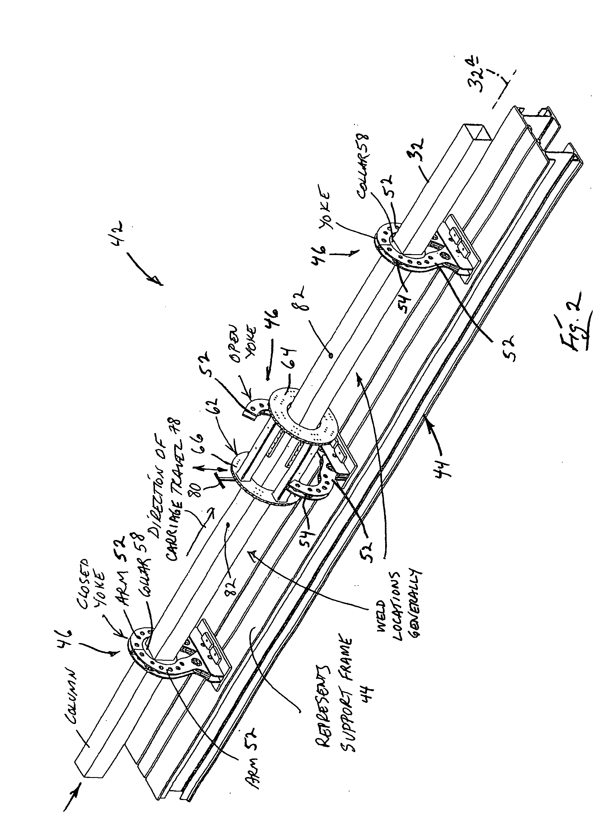
[0016] As will be seen from the description which is presented below, following deployment-attachment of the beam mounts in a cluster of such mounts at a given location along the length of a supported column, the appropriate supporting swing-arm yoke can be “opened” to allow the carriage to be shifted downwardly (i.e., downstream) along the column toward the next site for beam-mount attachment. The rolling contact structure which is interposed the carriage and a supported column allows for such carriage movement, with appropriate clearance provided for the just-attached beam mounts. The manner in which previously supported and carried beam mounts were carried on the carriage allows these beam mounts and the carriage to “part company” with one another as the carriage shifts downwardly along the subject column.

Problems solved by technology

Such columns, however, can present challenges during manufacture, and later during assembly with beams, regarding which (in both cases) there are manufacturing and assembling steps wherein it is conventional that high heat (due to welding operations) is (or may be) involved.
Such heat can prove to be a difficult culprit (a) during manufacture where a column can warp or twist (even slightly) during cool-down, and (b) during building-frame assembly where extreme local hot regions created during welding operations can introduce similar undesirable, and often difficult to correct or manage, deformations.

Method used


Image

  • Rotational method and apparatus for welding beam-mount structure to the side(s) of a column
  • Rotational method and apparatus for welding beam-mount structure to the side(s) of a column
  • Rotational method and apparatus for welding beam-mount structure to the side(s) of a column

Examples


Embodiment Construction

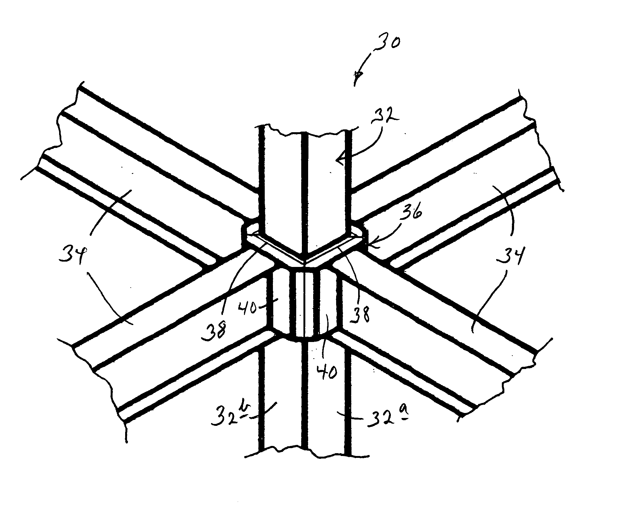
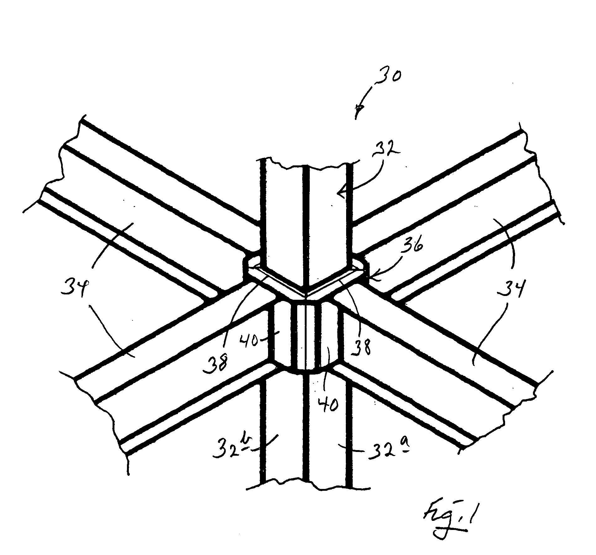
[0037] Turning now to the drawings, and referring first of all to FIG. 1, illustrated fragmentarily and generally, and also in a somewhat simplified form, at 30 in this figure are portions of a precision, close-tolerance structural building frame which has been constructed in accordance with the teachings of the above-referred to, prior-filed U.S. Patent Application. Frame structure 30 includes upright tubular, square cross section elongate steel columns, such as the single column shown at 32, two orthogonally related outside faces of which are seen in FIG. 1 at 32a, 32b.

[0038] Joined to the four orthogonally related faces, such as faces 32a, 32b, in column 32 are the ends of four horizontal I-beams, such as those shown at 34, with these I-beams being joined to column 32 through a style of collar interconnect structure 36 which has been constructed in accordance with the teachings of the referenced, prior-filed U.S. Patent Application. More specifically, collar interconnect structu...


PUM

PropertyMeasurementUnit
angleaaaaaaaaaa
lengthaaaaaaaaaa
resistanceaaaaaaaaaa

Abstract

A method and related apparatus for precision deploy-attaching beam-mount structure to the outside of an elongate column at plural, defined attachment sites that are distributed and spaced along the length of the column. The method involves (a) preparing an elongate column to act as a travel way for a carriage which is designed to transport and deploy beam-mount structure, shifting such a carriage progressively along the column from defined attachment site to defined attachment site, and at each such site, deploy-attaching from the carriage to the column the carriage-carried beam-mount structure.

Description

CROSS REFERENCE TO RELATED APPLICATION [0001] This application claims priority to the earlier filing date of U.S. Provisional Patent Application Ser. No. 60 / 503,071, filed Sep. 14, 2003 for “Rotational Method and Apparatus for Welding Beam-End Attaching Components to the Side of a Column”. The contents of that prior-filed, currently pending U.S. Provisional Application are hereby incorporated herein by reference.BACKGROUND AND SUMMARY OF THE INVENTION [0002] This invention pertains to building frame structure, and in particular to a method and apparatus for performing precision-placement, and deployment-attaching and welding, of plural beam-end attaching components, referred to also herein as beam mounts, and as beam-mount structure, to plural spaced regions, or sites, that are distributed along the outer sides of elongate, hollow-tube steel columns, which sites are disposed angularly about the long axes of such columns. Especially, it relates to such deployment-attachment and weldi...

Claims


Application Information

Patent Timeline
Patent Type & Authority Applications(United States)
IPC IPC(8): B23K31/12E04B1/24E04B1/26E04B5/10
CPCB23K31/12Y10T29/49634E04B1/26E04B5/10E04B2001/2415E04B2001/2454Y10T29/53996Y10T29/53543Y10T29/53961Y10T29/53539Y10T29/53548Y10T403/348Y10T29/53Y10T403/341B23K2201/28B23K2101/28
Inventor SIMMONS, ROBERT J.
Owner CONXTECH INC
Why Eureka
Try Eureka