
Control apparatus and method for internal combustion engine with variable compression ratio mechanism

a technology of compression ratio and control apparatus, which is applied in the direction of mechanical equipment, electric ignition installation, machines/engines, etc., can solve the problems of engine performance efficiency inevitably lowering and the anti-knock property of the engine, and achieve the effect of preventing the deviation of the ignition timing

Active Publication Date: 2005-03-17
NISSAN MOTOR CO LTD
View PDF3 Cites 23 Cited by
  • Summary
  • Abstract
  • Description
  • Claims
  • Application Information

AI Technical Summary

Benefits of technology

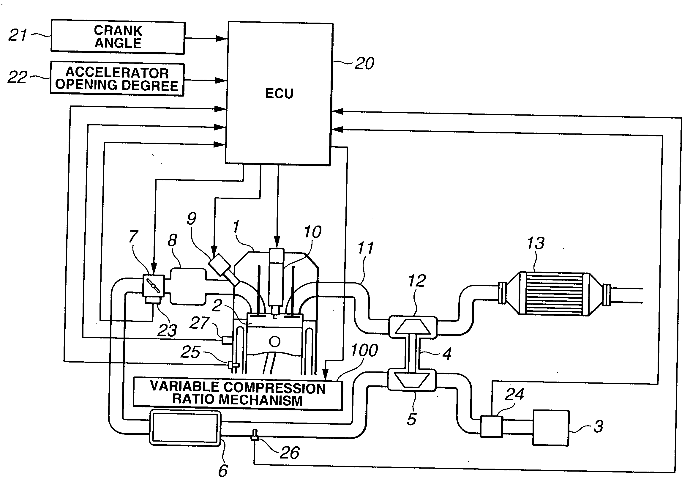
[0008] In a spark ignition type internal combustion engine having a variable compression ratio mechanism, a basic control of ignition can be attained by performing a basic ignition timing control in accordance with an actual compression ratio and the above-described knock control. Further, by performing an ignition timing learning control, it becomes possible, in each operating range of the engine, to prevent deviation of the ignition timing from an optimum value and attain optimum setting of the ignition timing.
[0010] In this connection, if a spark ignition type internal combustion engine has a variable compression ratio mechanism, it becomes possible to absorb an aged deterioration of the engine and a variation of the individual engine itself by changing a set compression ratio every operating condition of the engine in place of correction of the ignition timing. As compared with the case correction is made by the ignition timing, it becomes possible to avoid knock of the engine while improving the fuel consumption of the engine by selecting a compression ratio that allows the ignition timing to go closer to an optimum value.

Problems solved by technology

However, it is heretofore known that an anti-knock property of an engine is lowered due to aged deterioration such as deposit.
In this instance, retardation of the ignition timing is increased gradually, thus causing a problem that the performance efficiency of the engine is inevitably lowered.

Method used


Image

  • Control apparatus and method for internal combustion engine with variable compression ratio mechanism
  • Control apparatus and method for internal combustion engine with variable compression ratio mechanism
  • Control apparatus and method for internal combustion engine with variable compression ratio mechanism

Examples


first embodiment

[0058]FIG. 10 is a flowchart for correction of a set compression ratio according to the present invention, which is executed in ECU 20.

[0059] In step S101, an ignition timing learning correction value is read.

[0060] In step S102, it is determined whether or not an absolute value of the ignition timing correction value is larger than a predetermined value.

[0061] If the absolute value of the ignition timing correction value is larger than the predetermined value, the control processing goes to step S103.

[0062] In step S103, by reference to a table for determining a set compression ratio correction value in accordance with an ignition timing learning correction value, a set compression ratio correction value is determined from an ignition timing learning correction value. Herein, the set compression ratio correction value is determined so that the set compression ratio is corrected increasingly toward the low compression ratio side with increase in the ignition timing learning corre...

second embodiment

[0066] Then, the second embodiment will be described.

[0067] The second embodiment is configured, in contrast to the first embodiment, to further correct the ignition timing learning correction value on the basis of cooling water temperature Tw representative of a warm-up condition of the engine, intake air temperature Ta representative of an environmental condition and air / fuel ratio A / F (a deviation from a target A / F and representative of a deviation of a fuel control of the engine) thereby establishing a higher correlation between the aged deterioration of the engine and the ignition timing learning correction value and performing a better compression ratio correction.

[0068]FIG. 12 is a flowchart showing a set compression ratio correction according to the second embodiment, which is executed in ECU 20.

[0069] In step S201, an ignition timing learning correction value is read.

[0070] In step S202, cooling water temperature Tw, intake air temperature Ta and air / fuel ratio A / F are r...

third embodiment

[0082] Then, the third embodiment will be described.

[0083] The third embodiment aims at determining the more assured set compression ratio correction value by restricting the learning correction range of the compression ratio.

[0084]FIG. 14 is a flowchart showing a set compression ratio correction which is executed in ECU 20, and FIG. 15 is a view showing a separated condition of learning correction ranges for a compression ratio.

[0085] A, B ranges are limited to the ranges in which the set compression ratio is maximum and the engine load is relatively high. For this reason, the lower limit of the ranges is defined by the engine load (air quantity equivalent value Tp, APO, TVO or the like) and the upper limit is defined by the maximum compression ratio limit line of a basic set compression ratio map.

[0086] C, D ranges are determined at both the upper limit and the lower limit by compression ratio setting.

[0087] Further, defined as E, F ranges are high load ranges. On the high spe...


PUM


Abstract

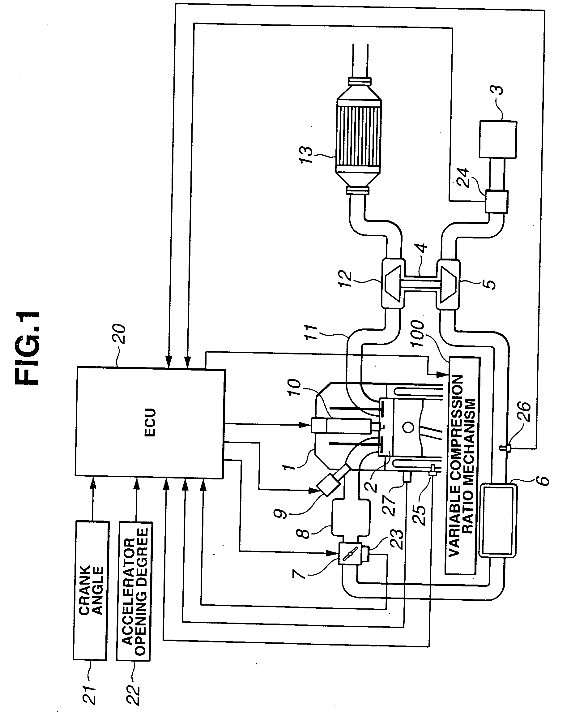
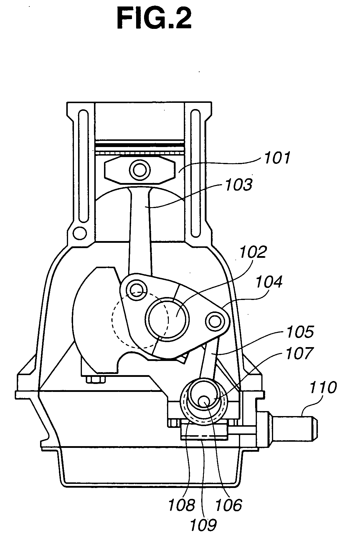
A control apparatus for an internal combustion engine includes a variable compression ratio mechanism capable of varying a compression ratio of the engine, a compression ratio setting section that sets a compression ratio to be attained by the variable compression ratio mechanism in accordance with an operating condition of the engine, a knock detecting section that detects a knock occurrence state, an ignition timing learning correcting section that determines a learning correction value of an ignition timing in accordance with the knock occurrence sate, and a compression ratio correcting section that corrects the compression ratio set by the compression ratio setting section in accordance with the learning correction value of the ignition timing. A control method is also provided.

Description

BACKGROUND OF THE INVENTION [0001] The present invention relates to a control apparatus and method for an internal combustion engine having a variable compression ratio mechanism. [0002] A typical conventional ignition timing control system for an internal combustion engine is adapted to determine an ignition timing in accordance with engine speed and load. [0003] In contrast to this, it is proposed, as disclosed in Unexamined Japanese Patent Publication No. 2001-280228, to optimize an ignition timing with consideration of valve timing. This is for taking into account decrease in combustion speed that is caused when a variable valve operating mechanism is used to perform a so-called non-throttle operation or when an internal EGR ratio (remaining gas ratio) is controlled by valve overlap. Namely, in such a non-throttle operation, decrease in combustion speed is caused when a set intake valve closing timing is advanced to decrease an effective compression ratio. Further, in such an in...

Claims


Application Information

Patent Timeline
IPC IPC(8): F02B23/00F02B75/04F02B75/32F02B77/08F02D15/02F02P5/152F02P5/153F16C7/00
CPCF02B75/045F02B75/048F02B77/085Y02T10/46F02D35/027F02P5/152F02D15/02Y02T10/40
Inventor SUGIYAMA, TAKANOBUTAKEMURA, SHINICHINODA, TORUHIYOSHI, RYOSUKEAOYAMA, SHUNICHI
Owner NISSAN MOTOR CO LTD
Learn More