Fuel injection valve
a technology of fuel injection valve and valve body, which is applied in the direction of fuel injection apparatus, fuel injection with shape memory alloys, and feed systems, etc., can solve the problem of not allowing the setting of an optimum spray angle, and achieve the effect of improving the exhaust emission of the engin
- Summary
- Abstract
- Description
- Claims
- Application Information
AI Technical Summary
Benefits of technology
Problems solved by technology
Method used
Image

Examples
first embodiment
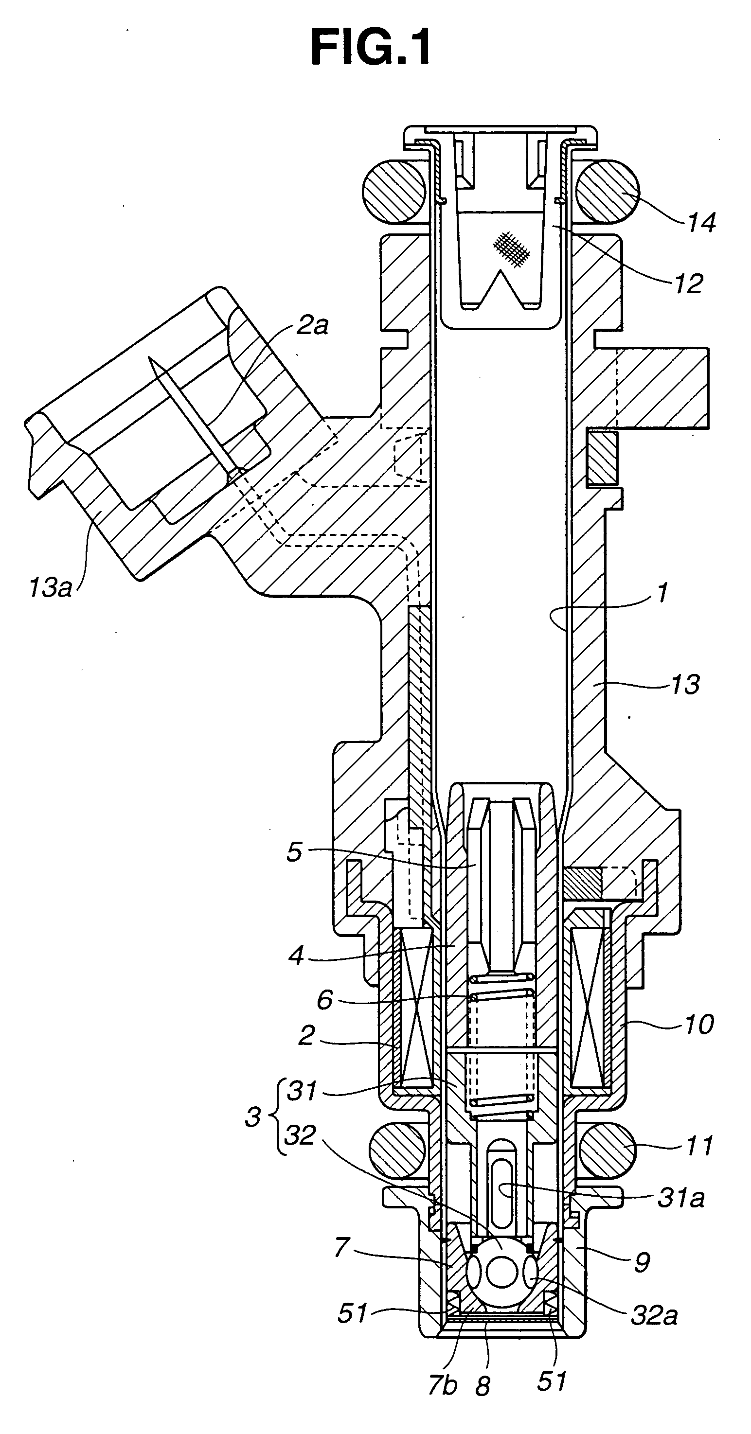
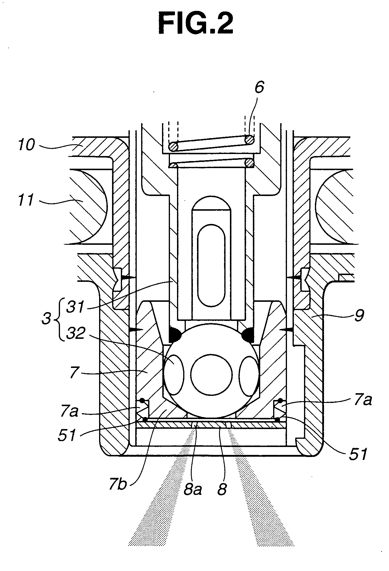
[0015] Referring to FIGS. 1-3, there is shown first embodiment of the present invention. Referring to FIG. 1, the fuel injection valve comprises a casing pipe 1 made of a magnetic material, an electromagnetic coil 2 fixedly mounted on the outer periphery of casing pipe 1, and a valve element 3 axially slidably arranged through casing pipe 1 and including a tubular anchor 31 and a ball 32 integrated together by welding.
[0016] A fuel passage opening 31a is formed in the lower peripheral wall of anchor 31, and a plurality of flat surfaces 32a are provided on the periphery of ball 32 by machining. Fuel flowing outward of anchor 31 through fuel passage opening 31a runs toward the front end of the fuel injection valve through a clearance between flat surfaces 32a and the inner wall of a valve seat 7 as will be described later. A tubular spring housing 4 is fixedly mounted on the inner wall of casing 1 above valve element 3 (anchor 31) as viewed in FIG. 1 with a predetermined clearance pro...
second embodiment
[0027] Moreover, in the second embodiment, a heater 55 is integrally provided to the inside of cap 9 to heat deformable member 1. This structure allows control of the temperature conditions of deformable member 51 by controlling energization of heater 55 in accordance with the required spray angle, thus achieving control of the displacement amount or position of nozzle plate 8, resulting in change in spray angle with higher flexibility.
[0028] Referring to FIG. 6, there is shown third embodiment of the present invention. In the third embodiment, deformable member 51 is supported to casing pipe 1 as a fixed end. As distinct from the first and second embodiments, in the third embodiment, the fuel injection valve is constructed such that, when deformable member 51 expands, valve seat 7 is close to nozzle plate 8 with, whereas, when it contracts, valve seat 7 is separate from nozzle plate 8. Alternatively, the fuel injection valve may be constructed such that, when deformable member 51 e...
fourth embodiment
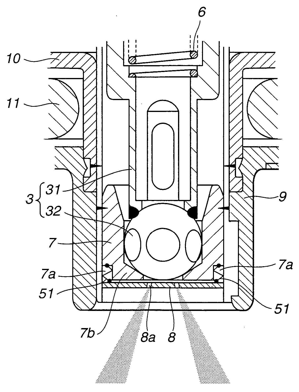
[0030] Referring to FIG. 7, there is shown fourth embodiment of the present invention. In the forth embodiment, nozzle plate 8 itself is formed of a shape memory alloy. The peripheral edge of nozzle plate 8 formed of a shape memory alloy is connected to the inner peripheral wall of casing pipe 1. The outer periphery of nozzle plate 8 deforms in accordance with the temperature to have the center portion with nozzle holes 8a moving parallel.
[0031] In the fourth embodiment, the outer periphery of nozzle plate 8 deforms in accordance with the temperature to achieve change in distance between valve seat 7 and the center portion of nozzle plate 8 having nozzle holes 8a, i.e. space between valve-seat portion 7b of valve seat 7 and nozzle plate 8, thus achieving change in spray angle.
[0032] When nozzle plate 8 is formed of a shape memory alloy, the portions for defining nozzle holes 8a are constructed to be deformable also, thereby achieving change not only in the space between valve-seat ...
PUM
 Abstract
Description
Claims
Application Information