Packaging machine

Inactive Publication Date: 2005-03-17
MULTIVAC SEPP HAGGENMULLER GMBH & CO KG
View PDF12 Cites 15 Cited by
  • Summary
  • Abstract
  • Description
  • Claims
  • Application Information

AI Technical Summary

Benefits of technology

[0007] It is an advantage of the invention to provide a torsion-proof shaft, on which the two engagement elements are arranged as fixed against rotation, as this enables a simple and economical solution to the problem on which the invention is based. Additionally it is thereby possible to retrofit old plants without great constructional outlay, by subsequently mounting the two already existing engagement elements, supported rotatably on axles, as fixed against rotation on the shaft.
[0008] It is yet another advantage of the invention to provide a drive device which jointly drives the first and second engagement elements. In this way the transport device is driven at two points by two drive devices, making it possible for introduction of the load on to the transport means to take place at several points, so it is reduced per introd

Problems solved by technology

A plant which is longer than 10 meters cannot therefore be impleme

Method used


Image

  • Packaging machine
  • Packaging machine
  • Packaging machine

Examples


Embodiment Construction

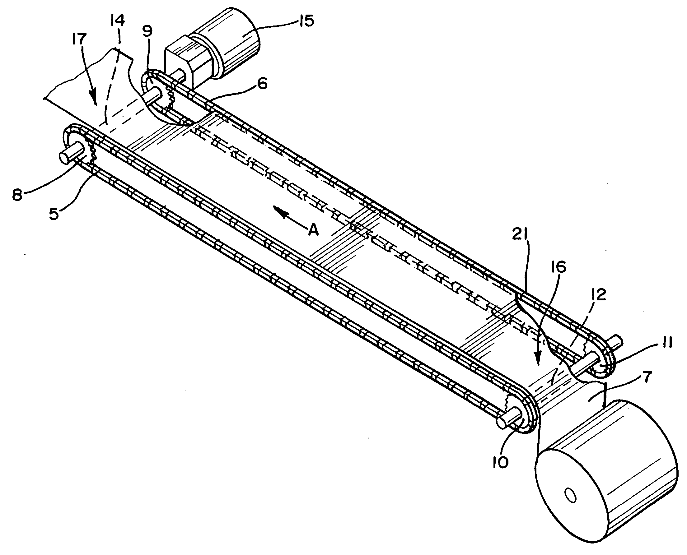
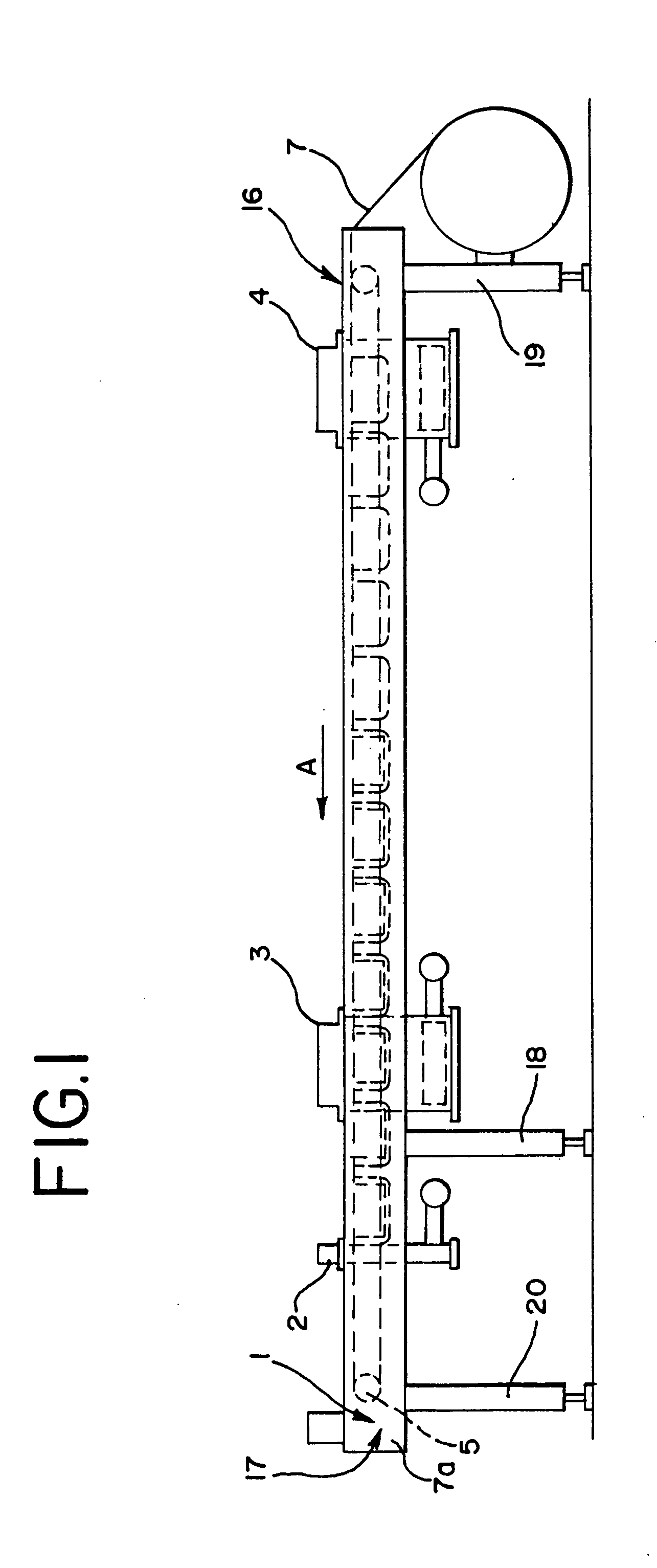
[0016] Referring to FIG. 1, a packaging machine according to a first embodiment example has a frame 1, containing two frame parts arranged parallel to one another in the longitudinal direction, only frame part 1a being seen in FIG. 1. The packaging machine transports a length of packaging material 7 from an inlet 16 on an entrance side to an outlet 17 on an exit side in transport direction A. The frame parts are carried by pairs of supporting legs 18, 19 and 20. Along frame parts 1a are arranged working stations 2, 3 and 4, at which the length of packaging material is processed. Transport of the length of packaging material 7 takes place via transport chains 5 and 6 in the form of continuous chains.

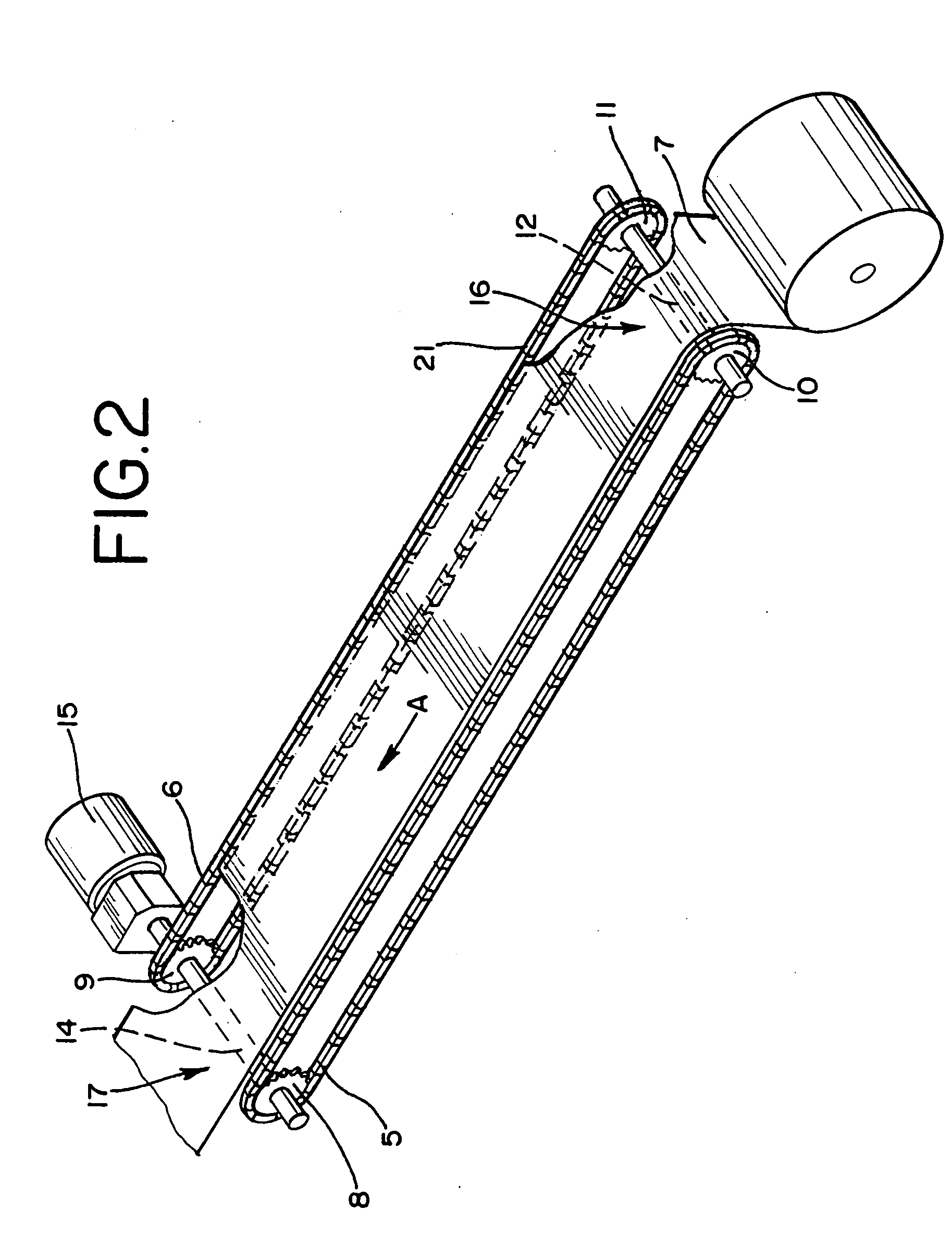
[0017] In FIG. 2 and all further FIGS. 3 to 5, to simplify legibility of the figures, illustration of the frame parts has been dispensed with. According to FIG. 2 a first chain wheel 8 is allocated to the first frame part at the outlet 17 and a first engagement element 10, also construct...


PUM

PropertyMeasurementUnit
Lengthaaaaaaaaaa
Transport propertiesaaaaaaaaaa

Abstract

The present invention relates to a packaging machine which has transport means in the form of two transport chains (5, 6) for lateral grasping and transporting of a length of material (7) consisting of packaging material. In particular with longer plants above approximately 10 meters in transport length the stretching property of the transport chains owing to the load has a marked effect on the precision of the transport distance. This results in fluctuations of the transport distance between the two transport chains and therefore distortions of the length of material, which, depending on the type of packaging material, can even lead to tearing of the length of material. In order to minimize these fluctuations, the first transport means (5) has a first engagement element (10) engaging in the first transport means (5) and the second transport means (6) a second engagement element (11) engaging in the second transport means (6), the first engagement element (10) being coupled to the second engagement element (11) in such a way that the two engagement elements are synchronized.

Description

[0001] This application claims priority to U.S. Provisional Application Ser. No. 60 / 478,162, filed Jun. 13, 2004.FIELD OF THE INVENTION [0002] The present invention relates to a packaging machine and particularly to a packaging machine having a transport mechanism. BACKGROUND OF THE INVENTION [0003] An exemplary packaging machine can be seen in DE 2 123 133, incorporated herein by reference. Such a packaging machine has a frame having two frame parts arranged parallel to one another in the longitudinal direction. At one end of the two frame parts chain wheels are provided in each case, via which run two transport chains in the form of continuous chains. The individual chain links of the transport chains are equipped with clamps which hold a length of packaging material, such as a foil, at the edges. When the chain links come into engagement with the chain wheels, the clamps open, so the length of packaging material is inserted into the clamps. When the chain links are released from ...

Claims


Application Information

Patent Timeline
IPC IPC(8): B65B41/14B65H20/16
CPCB65H20/16B65B41/14
Inventor NATTERER, JOHANN
Owner MULTIVAC SEPP HAGGENMULLER GMBH & CO KG
Why Eureka
Try Eureka