Electro-luminescence display device and method of fabricating the same

a technology of light-emitting display and e-luminescence, which is applied in the direction of discharge tube luminescent display, discharge tube/lamp details, electric discharge lamps, etc., can solve the problems of low light emission efficiency and brightness of the device, high power consumption, and high power consumption, so as to prevent material waste, reduce working hours, and improve production yield

Active Publication Date: 2005-03-17
LG DISPLAY CO LTD
View PDF3 Cites 5 Cited by
  • Summary
  • Abstract
  • Description
  • Claims
  • Application Information

AI Technical Summary

Benefits of technology

[0015] Accordingly, it is an object of the present invention to provide an electro-luminescence device and a method of fabricating the same capable of reducing working hours and preventing a waste of materials to improve a production yield by testing an adhesive level of a pad and a connection film of a driving circuit to a conductive film without requiring a separate destructive testing process.

Problems solved by technology

Thus the PDP is most advantageous to be made light and large-sized, but has disadvantages that the light emission efficiency and brightness thereof are low and its power consumption is high.
Whereas, the LCD has a disadvantage that the power consumption is high because the LCD is difficult to be made large-sized and adopts a backlight unit.
Further, the LCD has a disadvantage that there is a high optical loss caused by optical devices such as a polarizing filter, a prism sheet and a diffusion panel, and its viewing angle is narrow.
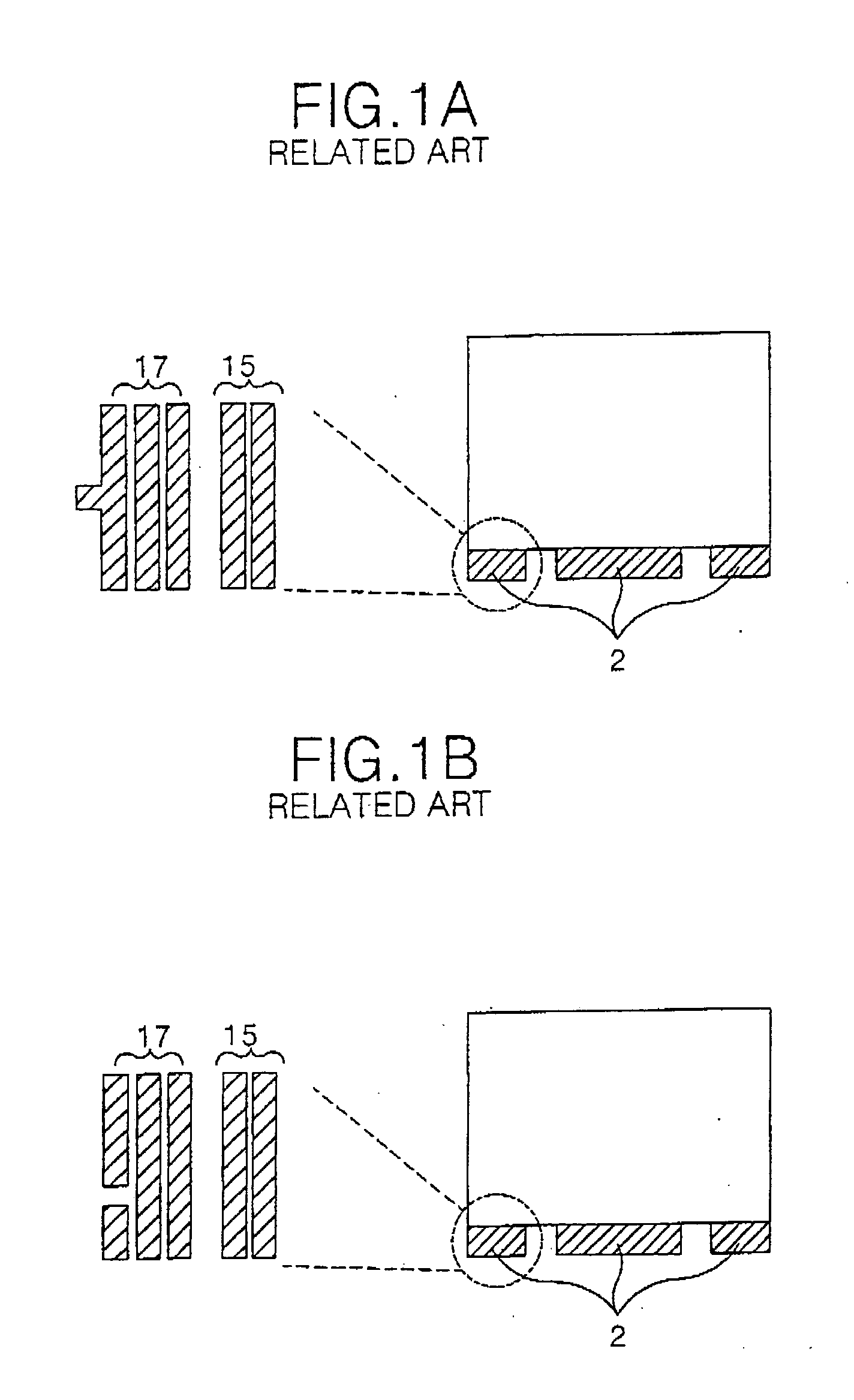
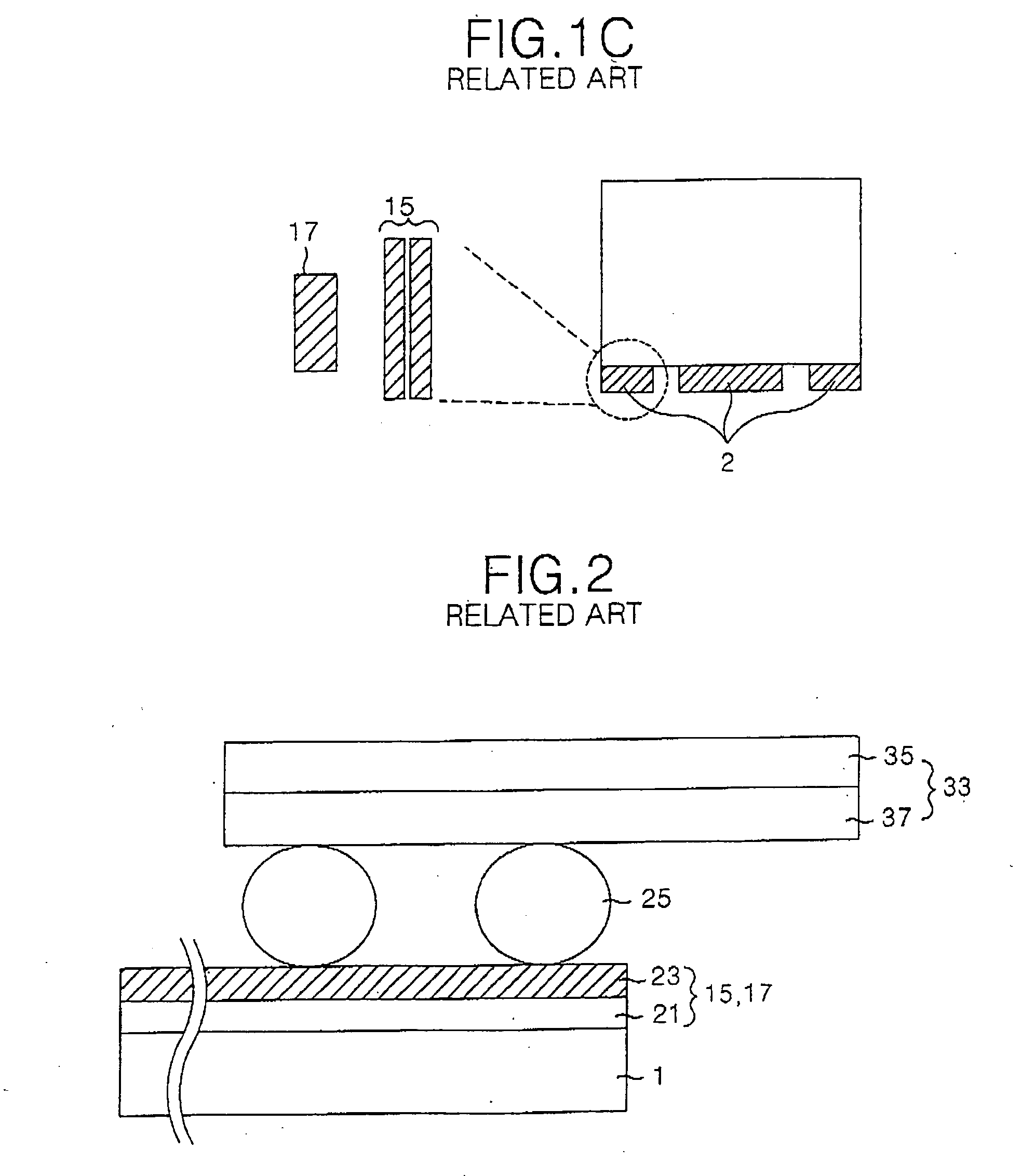
Hereby, working hours needed to fabricate the EL display device becomes long by the number of times that the testing process is being performed.

Method used


Image

  • Electro-luminescence display device and method of fabricating the same
  • Electro-luminescence display device and method of fabricating the same
  • Electro-luminescence display device and method of fabricating the same

Examples


Embodiment Construction

[0030] Reference will now be made in detail to the preferred embodiments of the present invention, examples of which are illustrated in the accompanying drawings.

[0031] Hereinafter, the preferred embodiments of the present invention will be described in detail with reference to FIGS. 3 to 6.

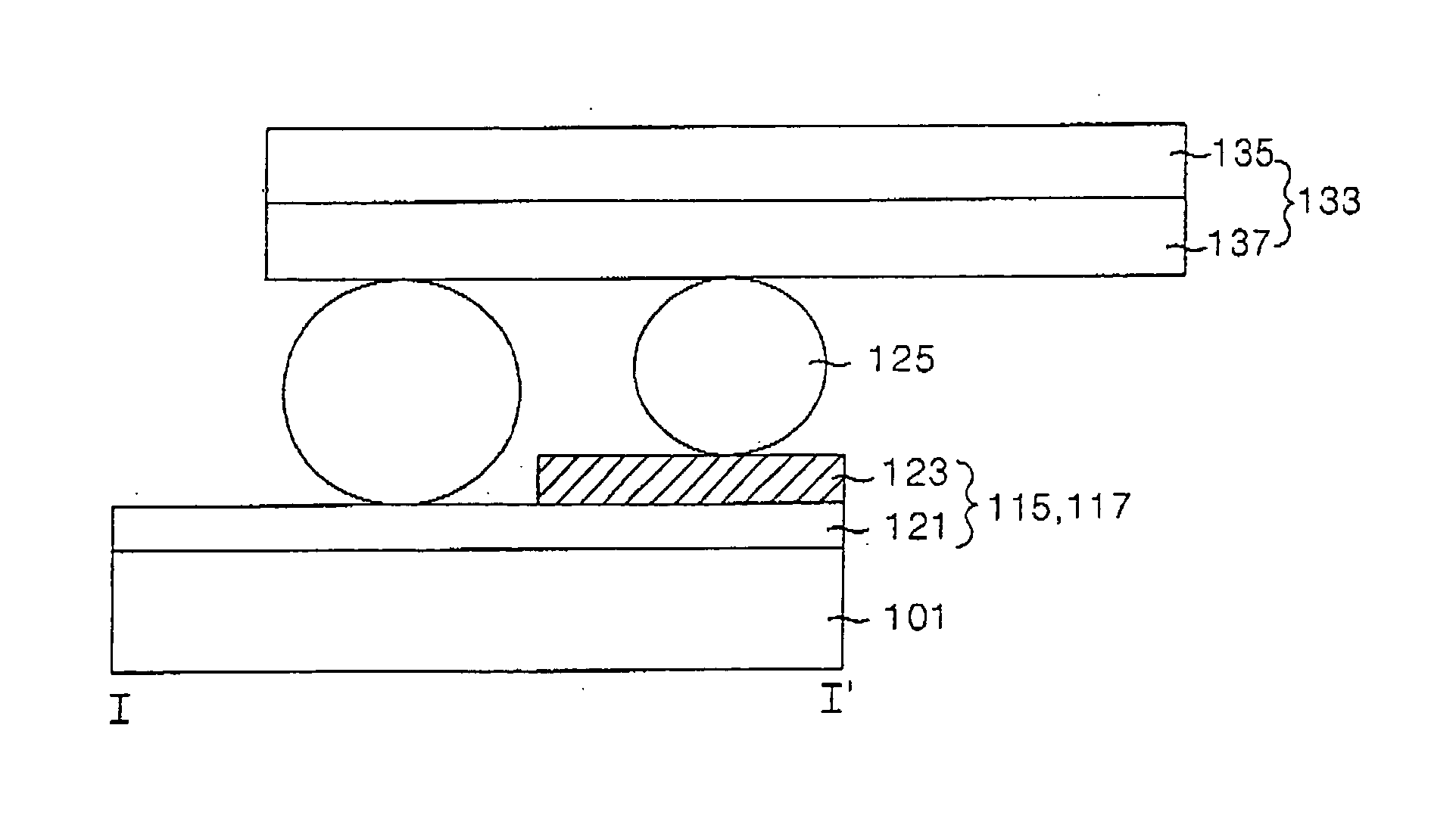
[0032]FIG. 3 is a schematic diagram of an electro-luminescence (EL) device according to an embodiment of the present invention.

[0033] The EL display device shown in FIG. 3 includes a display region 5 having a pixel matrix and a non-display region 4 having a pad connected to signal lines of the display region 5, on a substrate 101.

[0034] On the display region 5 of the EL display device, as shown in FIG. 4, an anode electrode 104 and a cathode electrode 112 are formed in a direction crossing each other. The anode electrode 104 is separated from its adjacent anode electrodes by a predetermined distance on the substrate 101. An insulating film 106 having an aperture at every EL cell region is for...


PUM


Abstract

An electro-luminescence display device and a method of fabricating the same capable of saving working hours needed to fabricate the electro-luminescence display device and preventing a waste of materials to improve a production yield of the electro-luminescence display device are disclosed. An electro-luminescence display device includes: a connection film being connected a driving circuit; a pad connected to the connection film in order to supply a driving signal from the driving circuit to a signal line formed on a substrate; a conductive film for connecting the connection film to the pad; and a plurality of dummy pads, each dummy pad including a transparent conductive layer, wherein at least one of the dummy pads is formed to expose the transparent conductive layer in order to test an adhesive level of the connection film and the pad by the conductive film.

Description

[0001] This application claims the benefit of Korean Patent Application No. P2003-52980 filed in Korea on Jul. 31, 2003, which is hereby incorporated by reference. BACKGROUND OF THE INVENTION [0002] 1. Field of the Invention [0003] The present invention relates to an electro-luminescence display device and, more particularly, to an electro-luminescence display device and a method of fabricating the same capable of saving working hours needed to fabricate the electro-luminescence display device and preventing a waste of materials to improve a production yield of the electro-luminescence display device. [0004] 2. Description of the Related Art [0005] In recently, there has been developed various flat panel displays with a reduced weight and bulk that are free from the disadvantage of a cathode ray tube CRT. Such flat panel displays include a liquid crystal display LCD, a field emission display FED, a plasma display panel PDP, and an electro luminescence (hereinafter, referred to as an...

Claims


Application Information

Patent Timeline
Patent Type & Authority Applications(United States)
IPC IPC(8): H01L27/32H05B33/10H05B33/00
CPCH01L27/3288H01L27/3223H10K59/88H10K59/179H10K71/70H05B33/10
Inventor LEE, JUNG HWANBAE, HYO DAE
Owner LG DISPLAY CO LTD
Why Eureka
Try Eureka