A/D converter calibration

Inactive Publication Date: 2005-03-17
INFINEON TECH AG
View PDF14 Cites 72 Cited by
  • Summary
  • Abstract
  • Description
  • Claims
  • Application Information

AI Technical Summary

Benefits of technology

[0005] An object of the present invention is to improve the utilization of the calibrating D/A converter resolution in flash type A/D converters

Problems solved by technology

The maximum achievable accuracy-speed performance of any A/D converter is limited by non-ideal effects associated with its building blocks.
Typically, the performance is limited by settling time, limited amplifier gain and component mismatch.
When designing high performance A/D converters, these limitations impose stringent demands on building blocks, leading to prolonged design time, lower yield and trade-offs between accuracy and speed.
However, the largest error amplitude

Method used


Image

  • A/D converter calibration
  • A/D converter calibration
  • A/D converter calibration

Examples


Embodiment Construction

[0026] In the following description the same reference designations will be used for the same or similar elements.

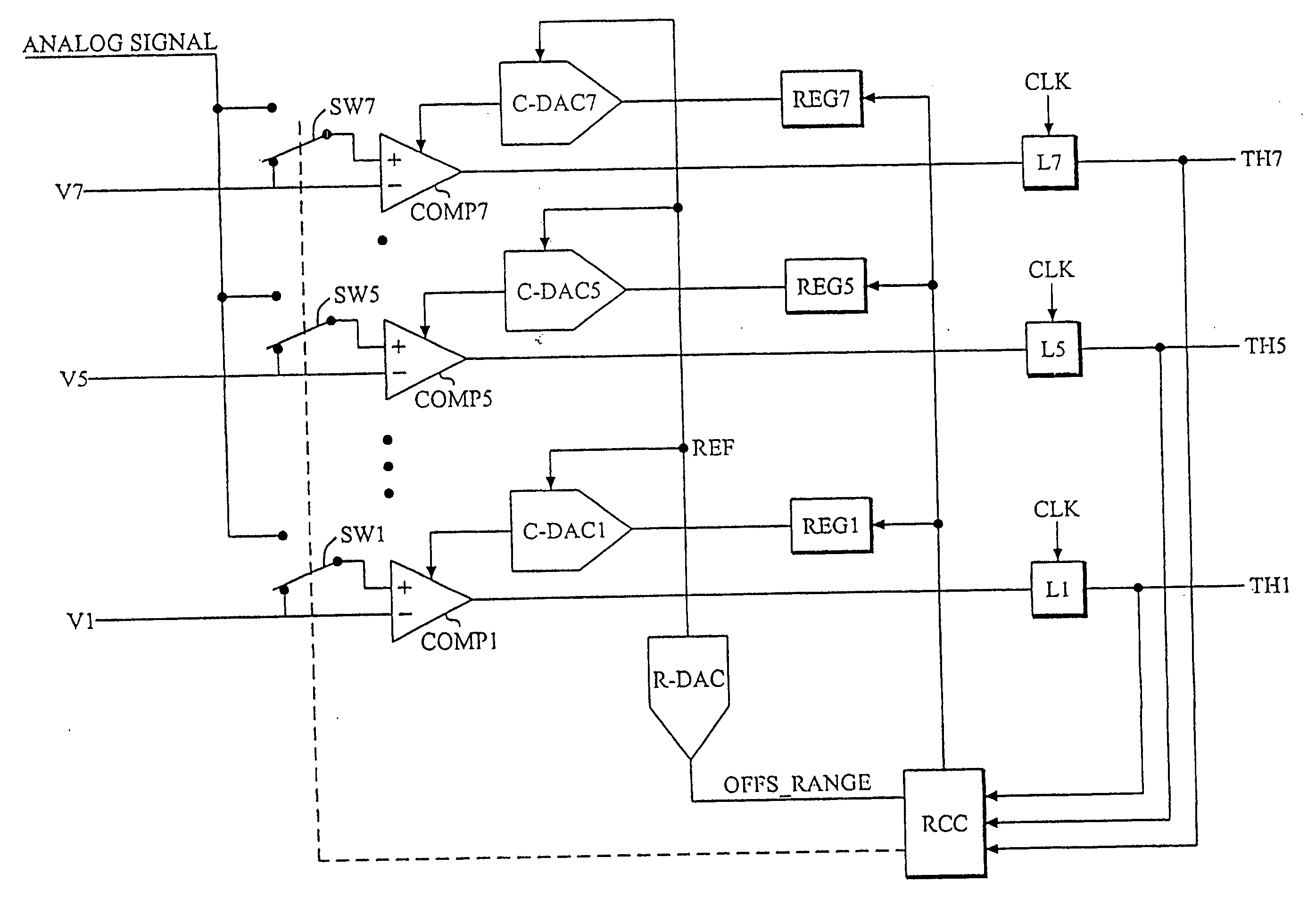
[0027] In this disclosure, a pipeline A / D converter will be used to illustrate the proposed range calibration method, but the method can also be applied to other types of converters, such as flash, sub-ranging, multi-bit delta-sigma and cyclic A / D converters or whenever a larger number of parallel offset calibrated comparators are used.

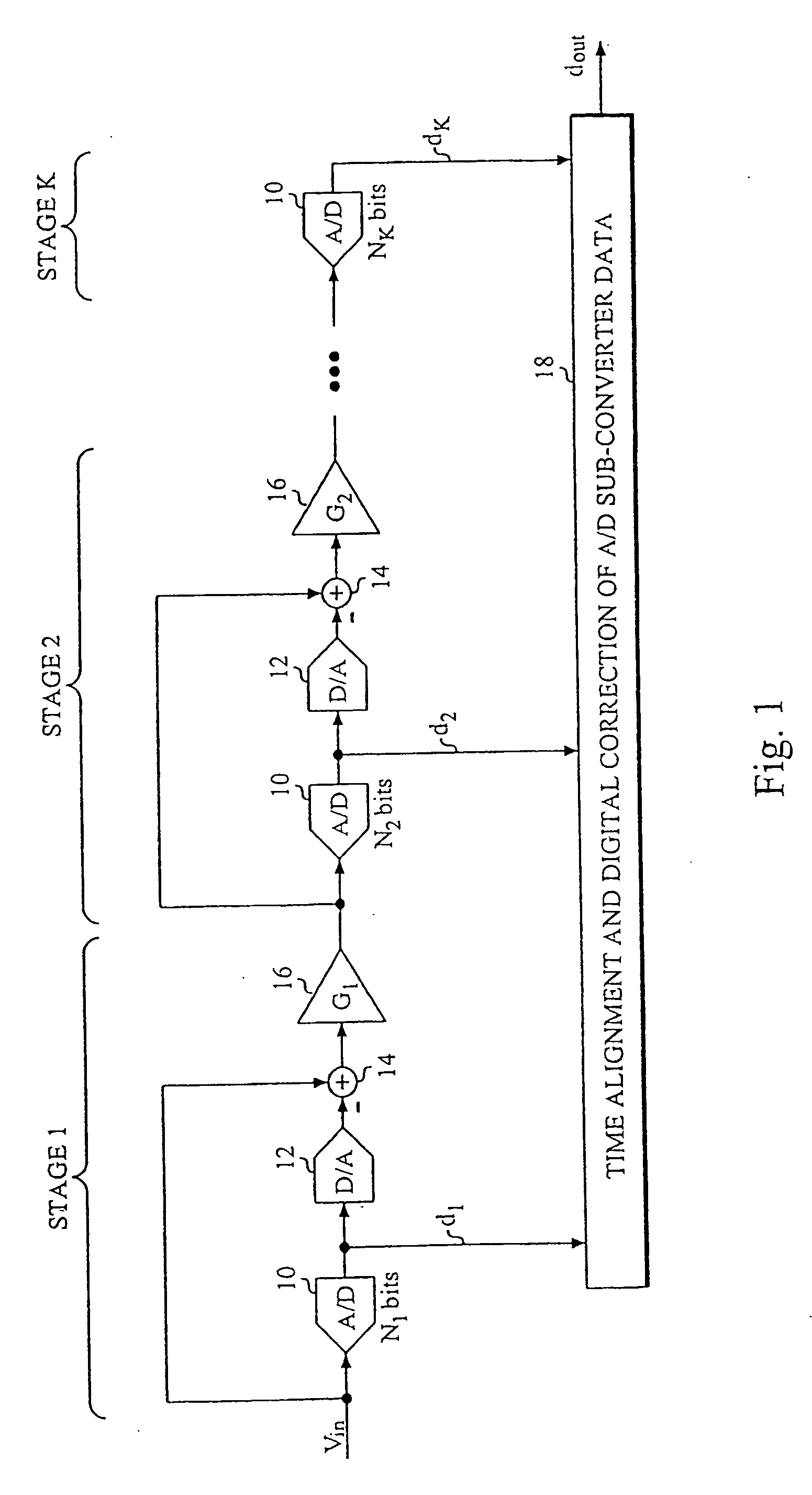
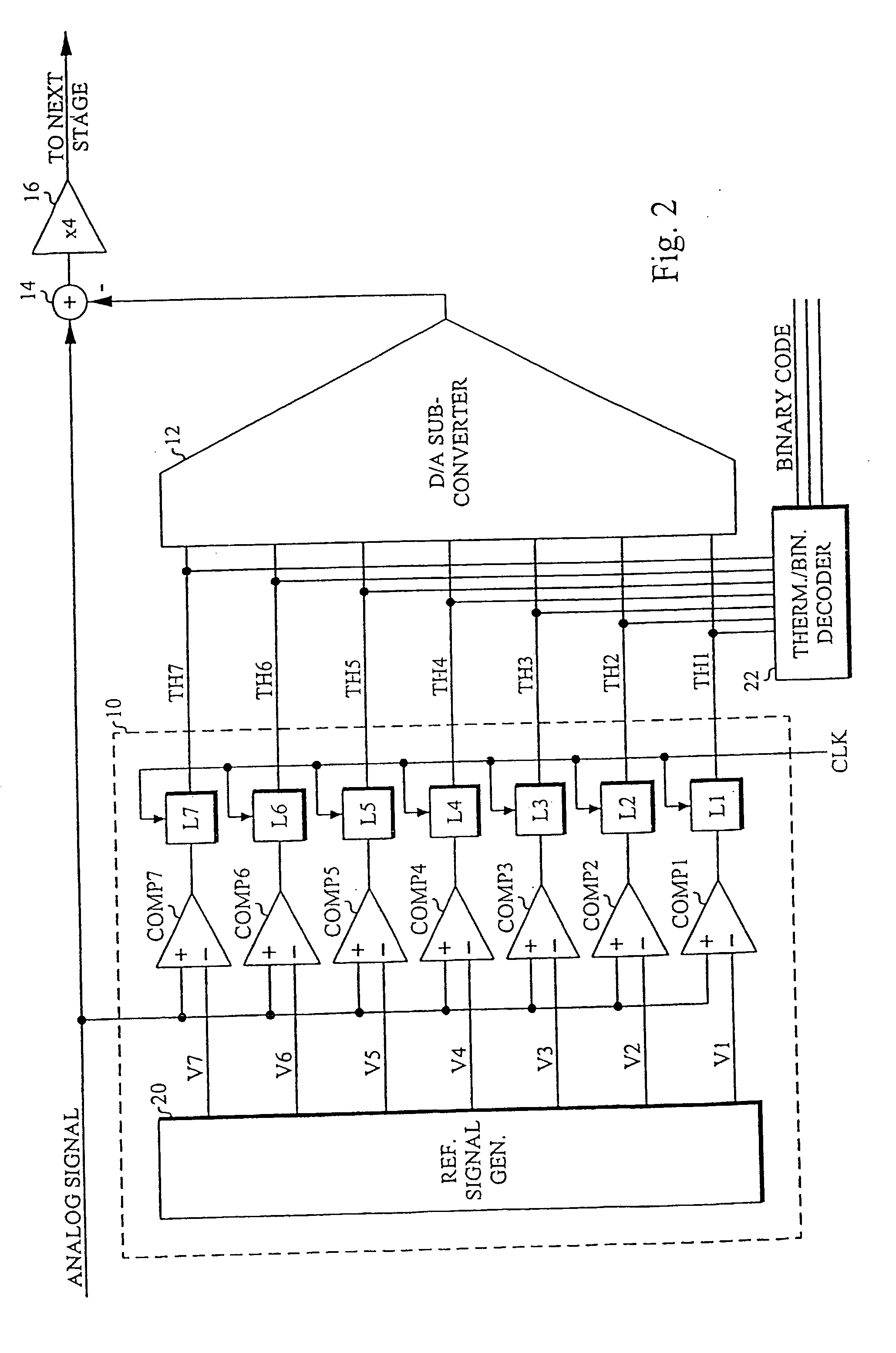
[0028]FIG. 1 is a block diagram of a typical pipeline A / D converter. An N-bit analog-to-digital conversion is performed in two or more stages, each stage extracting {N1, N2 . . . Nk} bits of information represented by the digital words {d1, d2 . . . dk}, where K is the number of pipeline stages. The first pipeline stage extracts the N1 most significant bits using an N1-bit A / D sub-converter 10. Then the estimated value is subtracted from the analog input signal Vin by using a D / A sub-converter 12 and an adder 14, leaving a residue contai...


PUM


Abstract

A D/A converter range calibration system in an A/D converter structure including a set of comparators with associated calibrating D/A converters includes means (RCC) for determining the offset error range for the entire set of comparators and means (R-DAC) for adjusting the dynamic range of each calibrating D/A converter to this offset error range.

Description

CROSS REFERENCE TO RELATED APPLICATION [0001] This application is a continuation of copending International Application No. PCT / SE03 / 00449 filed Mar. 17, 2003 which designates the United States, and claims priority to Swedish application no. 0200940-5 filed Mar. 25, 2002. TECHNICAL FIELD OF THE INVENTION [0002] The present invention relates to A / D (analog-to-digital) converters, and in particular how to improve the accuracy and yield of flash A / D converters or A / D sub-converters in pipeline, sub-ranging and cyclic A / D converters. BACKGROUND OF THE INVENTION [0003] The maximum achievable accuracy-speed performance of any A / D converter is limited by non-ideal effects associated with its building blocks. Typically, the performance is limited by settling time, limited amplifier gain and component mismatch. When designing high performance A / D converters, these limitations impose stringent demands on building blocks, leading to prolonged design time, lower yield and trade-offs between acc...

Claims


Application Information

Patent Timeline
IPC IPC(8): H03M1/10H03M1/36H03M1/70
CPCH03M1/361H03M1/1019H03M1/70
Inventor JANSSON, CHRISTER
Owner INFINEON TECH AG
Why Eureka
Try Eureka