
System and method for hole filling in 3D models

a technology of system and method, applied in the field of system and method for processing image data, can solve the problems of inability to physically reproduce an object with an incomplete surface definition, inability to penetrate one another, and large black regions on objects that are unrealistic and distracting

Inactive Publication Date: 2005-03-17
IBM CORP
View PDF5 Cites 56 Cited by
  • Summary
  • Abstract
  • Description
  • Claims
  • Application Information

AI Technical Summary

Problems solved by technology

After registration, scans do not form a single surface, but often interpenetrate one another due to acquisition errors, primarily along the line-of-sight in each scan.
These holes are the result of the scanning device not being able to sample parts of objects.
These are artificial holes that result from the scanning process and are unacceptable in almost all applications that use 3D models.
In any computer graphics applications or visual simulation, large black regions on an object are unrealistic and distracting.
In computer-aided design and manufacturing it is physically impossible to reproduce an object with an incomplete surface definition.
This works well for simple holes in almost flat surfaces, but for more complex cases it results in self-intersecting surfaces.
But, the method lacks control over properties of the surface, like curvature, which leads to surfaces not matching the topology of the object being modeled (scanned) in some cases.
This method suffers from the same lack of user control as the volumetric diffusion method.
However, the method does not operate properly if the scanner lines of sight do not adequately cover the volume outside the object.
Consequently, this method is slow especially for large models.
For large models, such as urban scenes or complex large works of art, the computational time is impractical for building a model in time to be used for the application.
The time to perform this calculation increases as N**2 for N points, making this approach not feasible for anything but relatively small point sets.

Method used


Image

  • System and method for hole filling in 3D models
  • System and method for hole filling in 3D models
  • System and method for hole filling in 3D models

Examples


Embodiment Construction

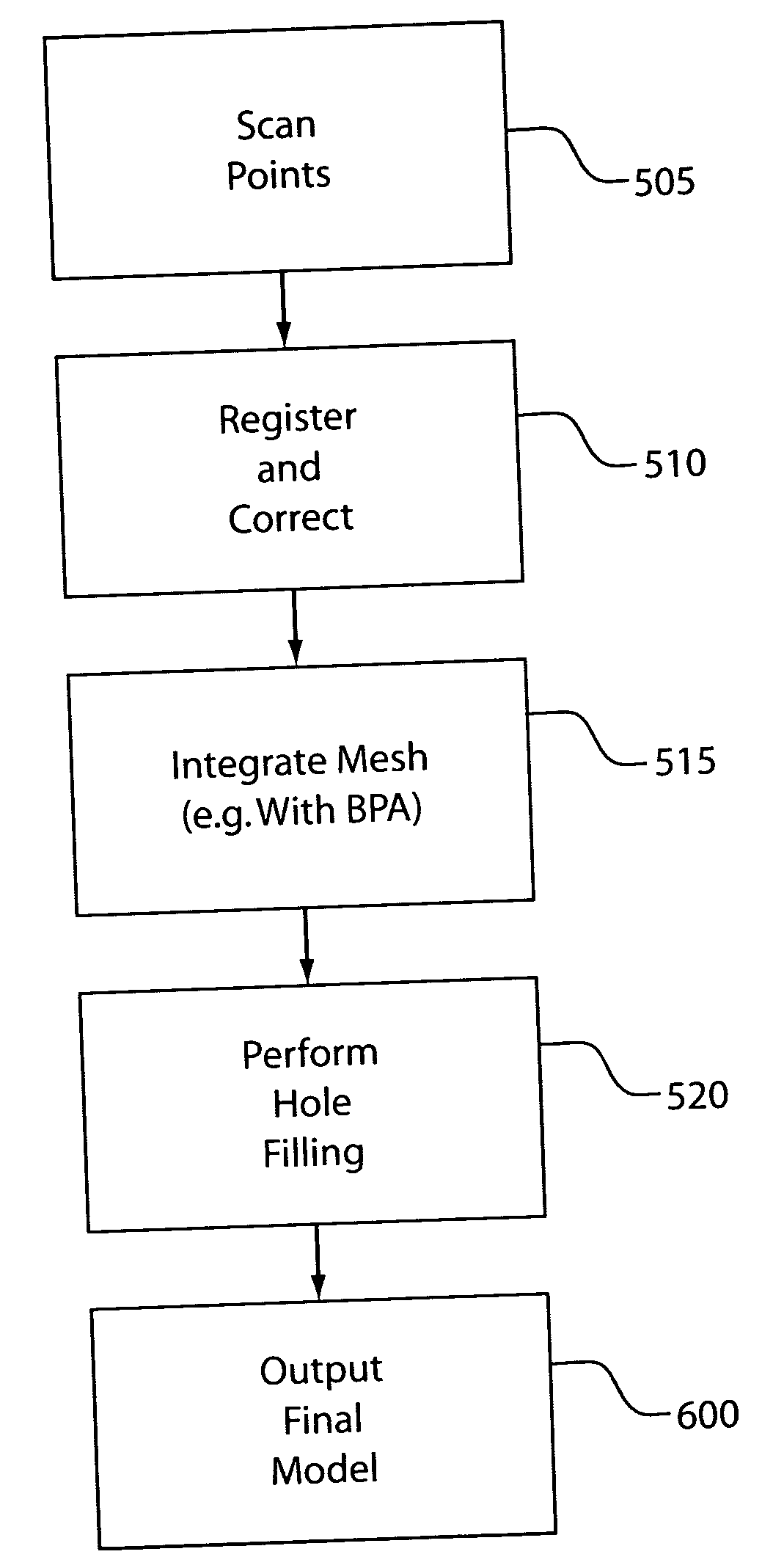
[0036] The present invention provides a method and system for filing holes in models produced by machine vision or computer graphics systems. For purposes of this disclosure, a model is a numerical definition of an object's shape. In particular, models produced from data captured by physical measurements of real objects are considered in detail (although this method could be applied to any numerical model of a surface). Holes are identified in the object, and the surface points, or vertices around the holes are also identified.

[0037] Based on these points, a Radial Basis Function (RBF) is fitted for each hole, which is used to define a volume throughout space. Points lying on the implicit surface that pass through this volume, where the RBF is zero, are extracted. Any method can then be used to integrate these new points to the existing mesh to complete the hole-filling.

[0038] Before integration of the holes, to form a single surface, overlapping scans may be averaged. In stitchin...


PUM


Abstract

A method for hole-filling in 3D models includes identifying vertices adjacent to hole boundaries in a mesh of points on a digital image and constructing a signed distance function based on vertices adjacent to hole boundaries. A Radial Basis Function is fit based on the constructed signed distance function and evaluated on a grid, which include the hole. The points on the hole surface are extracted and meshed to fill the hole.

Description

BACKGROUND OF THE INVENTION [0001] 1. Field of the Invention [0002] The present invention relates generally to methods and systems for processing image data, and more particularly, to methods and systems for computing complete surfaces from collections of coordinates representing points on an object's surface to generate images or for producing three-dimensional physical replicas or models of objects. [0003] 2. Description of the Related Art [0004] The creation of three-dimensional digital objects by scanning real objects or scenes has become common practice in computer graphics applications, computer-aided design and manufacturing, urban planning, training simulations and building construction. Computer graphics applications include computer games, e-commerce and virtual museums, for example. Computer-aided design applications include scanning objects to be used as starting points for the design of new products. For example, features on existing objects can be numerically deleted a...

Claims


Application Information

Patent Timeline
IPC IPC(8): G06T15/00G06T17/20
CPCG06T17/20
Inventor EL-DIN ELSHISHINY, HISHAM EMADBERNARDINI, FAUSTORUSHMEIER, HOLLY EDITH
Owner IBM CORP
Learn More