Bicubic surface rendering

a bicubic surface and surface technology, applied in the field of computer graphics, can solve the problems of affecting the rendering effect of objects, so as to reduce and minimize the number of computations.

Inactive Publication Date: 2005-03-17
3D SURFACES LLC
View PDF9 Cites 8 Cited by
  • Summary
  • Abstract
  • Description
  • Claims
  • Application Information

AI Technical Summary

Benefits of technology

The present invention provides a method and system for rendering bicubic surfaces of an object on a computer system. Each bicubic surface is defined by sixteen control points and bounded by four boundary curves, and each boundary curve is formed by boundary box of line segments formed between four of the control points. The method and system of include transforming only the control points of the surface given a view of the object, rather than points across the entire bicubic surface. Next, a pair of orthogonal boundary curves to process is selected. After the boundary curves have been selected, each of the curves is iteratively subdivided, wherein two new curves are generated with each subdivision. The subdivision of each of the curves is terminated when the curves satisfy a flatness threshold expressed in screen coordinates, whereby the number of computations required to render the object is minimized.
According to the system and method disclosed herein, the number of computations required for rendering of an object model is minimized by requiring that only two orthogonal curves of the surface be subdivided. As the number of computations is decreased, the entire rendering process can potentially be performed in real time. According to another aspect of the present invention, the computations for subdivision are performed by expressing the criteria of terminating the subdivision in the screen coordinates (SC). As the curvature is estimated based on how flat it appears to be in SC (pixels), rather than how curved it is in WC, the number of computations required may further be minimized. As a result, the possibility of rendering images in real time is further enhanced. In addition, allowing the curvature to be measured in SC units also allows for accommodating the distance to the viewer, thus giving the process an “automatic level of detail” capability.

Problems solved by technology

This process is executed off-line because the subdivision of the surfaces and the measurement of the resulting curvature are very time consuming.
This is due to the fact that the triangles resulting from subdivision must share the same vertices along the common surface boundary, otherwise cracks will appear between them.
For example, the process is slow because the subdivision is so computationally intensive, and is therefore often executed off-line.
In addition, as the subdivision of the tiles into triangles is done off-line, the partition is fixed, it may not account for the fact that more triangles are needed when the surface is closer to the viewer versus fewer triangles being needed when the surface is farther away.
Furthermore, each vertex or triangle plane normal needs to be transformed when the surface is transformed in response to a change of view of the surface, a computationally intensive process that may need dedicated hardware.

Method used


Image

  • Bicubic surface rendering
  • Bicubic surface rendering
  • Bicubic surface rendering

Examples


Embodiment Construction

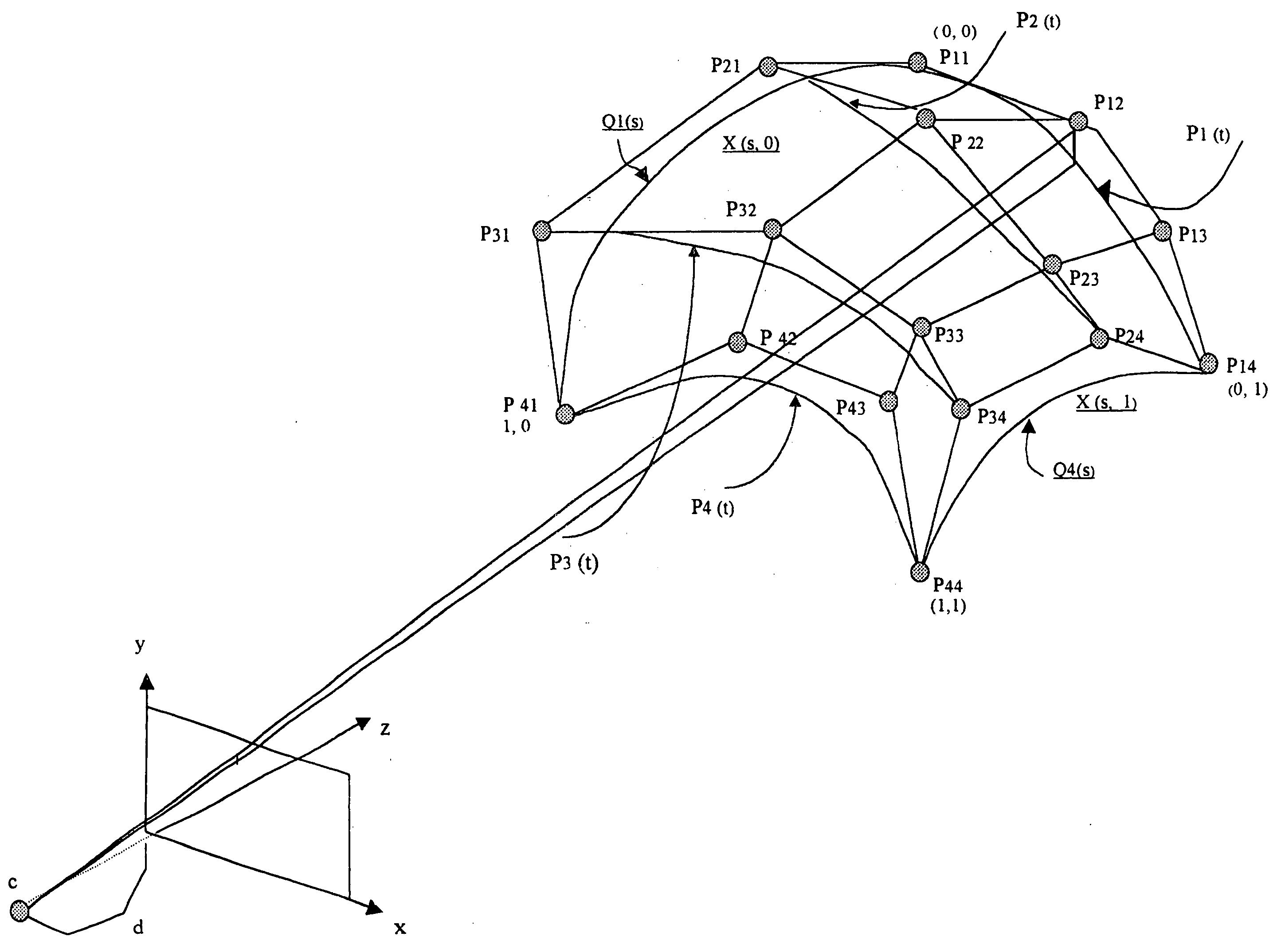
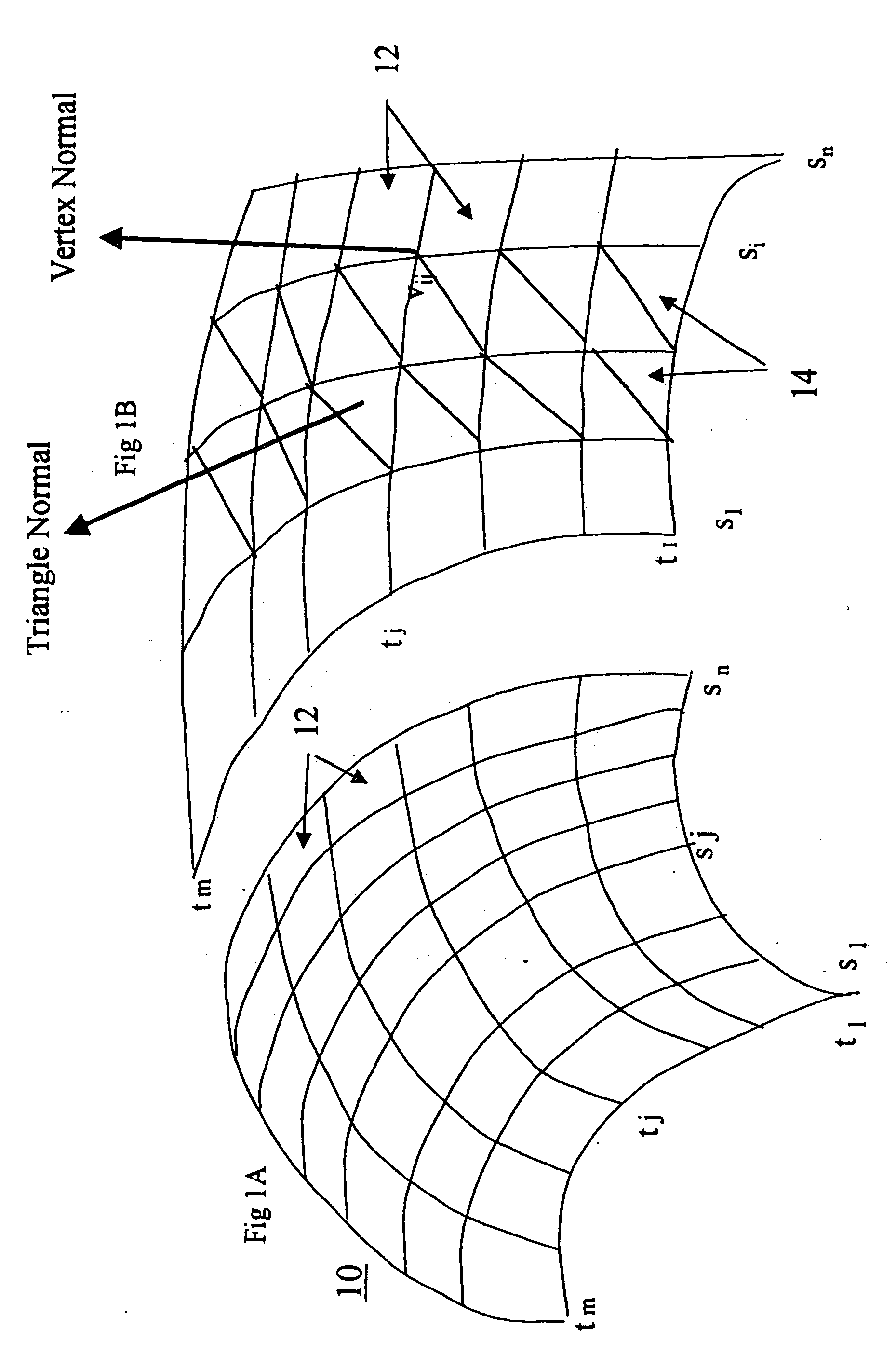
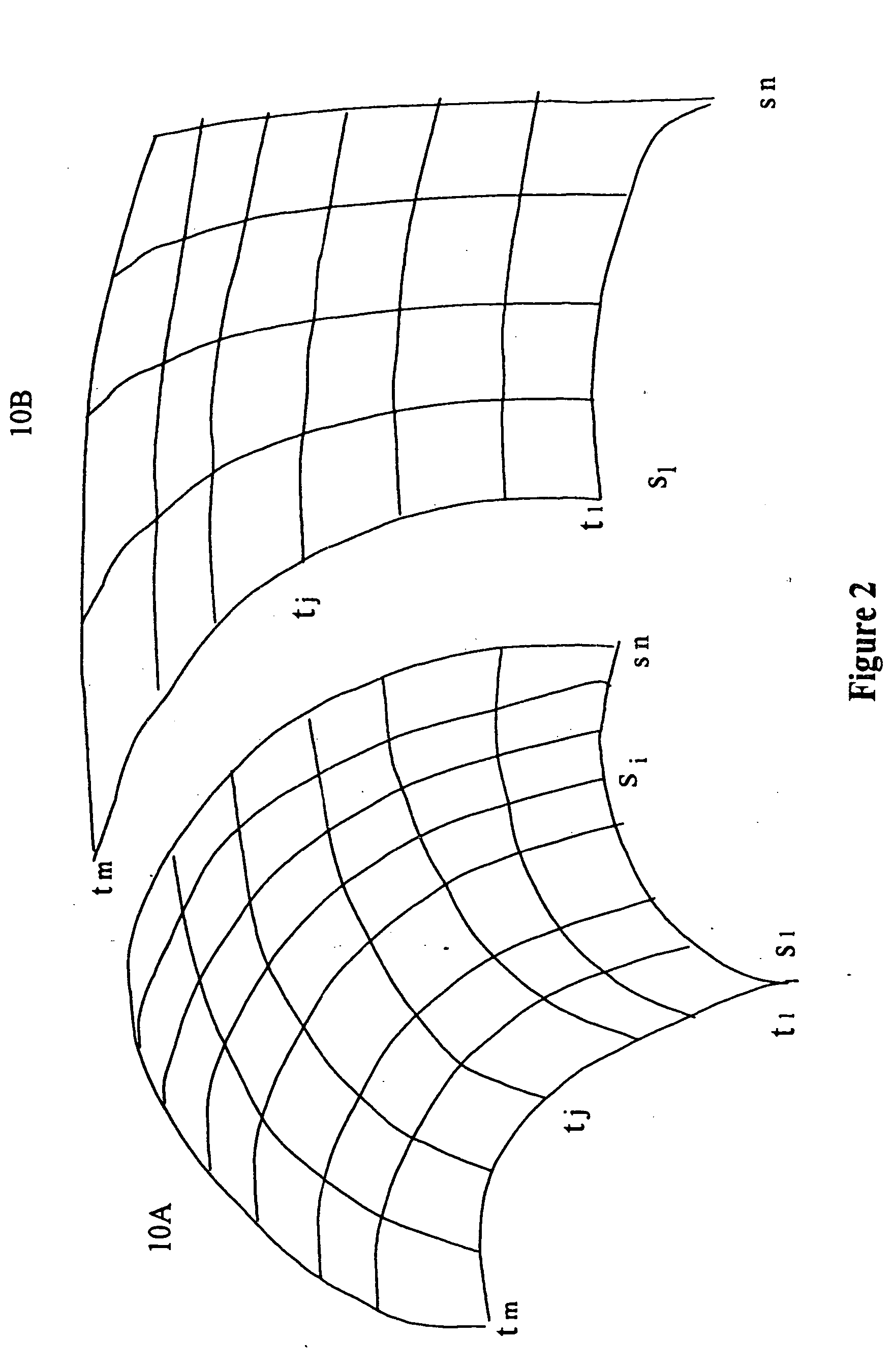
The present invention is directed to a method and apparatus for minimizing the number of computations required for the subdivision of bicubic surfaces into triangles. The following description is presented to enable one of ordinary skill in the art to make and use the invention and is provided in the context of a patent application and its requirements. Various modifications to the preferred embodiments and the generic principles and features described herein will be readily apparent to those skilled in the art. Thus, the present invention is not intended to be limited to the embodiments shown but is to be accorded the widest scope consistent with the principles and features described herein.

According to the present invention, the reduction in computations is attained by reducing the subdivision to the subdivision on only two orthogonal curves. In addition, the criteria for sub-division may be determined in SC. The description is provided with reference to Bezier surfaces for ill...


PUM


Abstract

A method and system for rendering bicubic surfaces of an object on a computer system. Each bicubic surface is defined by sixteen control points and bounded by four boundary curves, and each boundary curve is formed by boundary box of line segments formed between four of the control points. The method and system of include transforming only the control points of the surface given a view of the object, rather than points across the entire bicubic surface. Next, a pair of orthogonal boundary curves to process is selected. After the boundary curves have been selected, each of the curves is iteratively subdivided, wherein two new curves are generated with each subdivision. The subdivision of each of the curves is terminated when the curves satisfy a flatness threshold expressed in screen coordinates, whereby the number of computations required to render the object is minimized.

Description

FIELD OF THE INVENTION The present invention relates to computer graphics and more specifically to a method and apparatus for rendering a bicubic surface on a computer system. BACKGROUND OF THE INVENTION Object models are often stored in computer systems in the form of surfaces. The process of displaying the object (corresponding to the object model) generally requires rendering, which usually refers to mapping the object model onto a two dimensional surface. At least when the surfaces are curved, the surfaces are generally subdivided or decomposed into triangles in the process of rendering the images. In order to animate objects made of surfaces one applies special linear transformations to the vertices of the resulting triangles and to the normals to the surface at the triangle vertices. A special class of surfaces is “deformable” surfaces, that is surfaces that are plastic or elastic. Such surfaces can be decomposed into triangles but the decomposition as well as the normal cal...

Claims


Application Information

Patent Timeline
Patent Type & Authority Applications(United States)
IPC IPC(8): G06T11/20
CPCG06T17/30
Inventor SFARTI, ADRIAN
Owner 3D SURFACES LLC
Why Eureka
Try Eureka