Method of and apparatus for determining tire shapes

a technology of displacement gage and tire shape, which is applied in the direction of measurement devices, vehicle components, instruments, etc., can solve the problems of lowering determination accuracy, affecting the accuracy of tire shape determination, so as to reduce the weight of the apparatus and improve the accuracy of determination

Inactive Publication Date: 2005-03-17
THE YOKOHAMA RUBBER CO LTD
View PDF4 Cites 20 Cited by
  • Summary
  • Abstract
  • Description
  • Claims
  • Application Information

AI Technical Summary

Benefits of technology

[0004] An object of the present invention is to provide a method of and an apparatus for determining tire shapes, which make it possible both to reduce the weight of the apparatus and to improve determination accuracy when tire shapes are determined by using a non-contact displacement gage.
[0006] By allowing the displacement gage and the weight to move symmetrically along the scanning direction and synchronously with each other, it is possible to prevent the position of the center of gravity of the determination apparatus from shifting when the displacement gage is scanning, and thus to enhance the determination accuracy. Accordingly, when tire shapes are determined by using the non-contact displacement gage, it is possible to achieve both a reduction in the weight of the determination apparatus and an improvement in the determination accuracy. Of course, another displacement gage can be used as the weight.
[0008] By allowing the pair of displacement gages to move symmetrically along the scanning direction and synchronously with each other as described above, it is possible to prevent the position of the center of gravity of the determination apparatus from shifting when the displacement gage is scanning, and thus to enhance the determination accuracy. Accordingly, when tire shapes are determined by using the non-contact displacement gages, it is possible to achieve both a reduction in the weight of the determination apparatus and an improvement in the determination accuracy.

Problems solved by technology

However, in the portable determination apparatus reduced in weight, the weight of the displacement gage is relatively large.
Therefore, when the displacement gage scans a tire tread portion, the position of the center of gravity of the whole determination apparatus shifts, resulting in a tilt of the determination apparatus and a change in the distance between the tread surface and the displacement gage.
Accordingly, a problem arises that the determination accuracy is lowered.
As a result, determination work requires large amounts of effort and time.

Method used


Image

  • Method of and apparatus for determining tire shapes
  • Method of and apparatus for determining tire shapes
  • Method of and apparatus for determining tire shapes

Examples


first embodiment

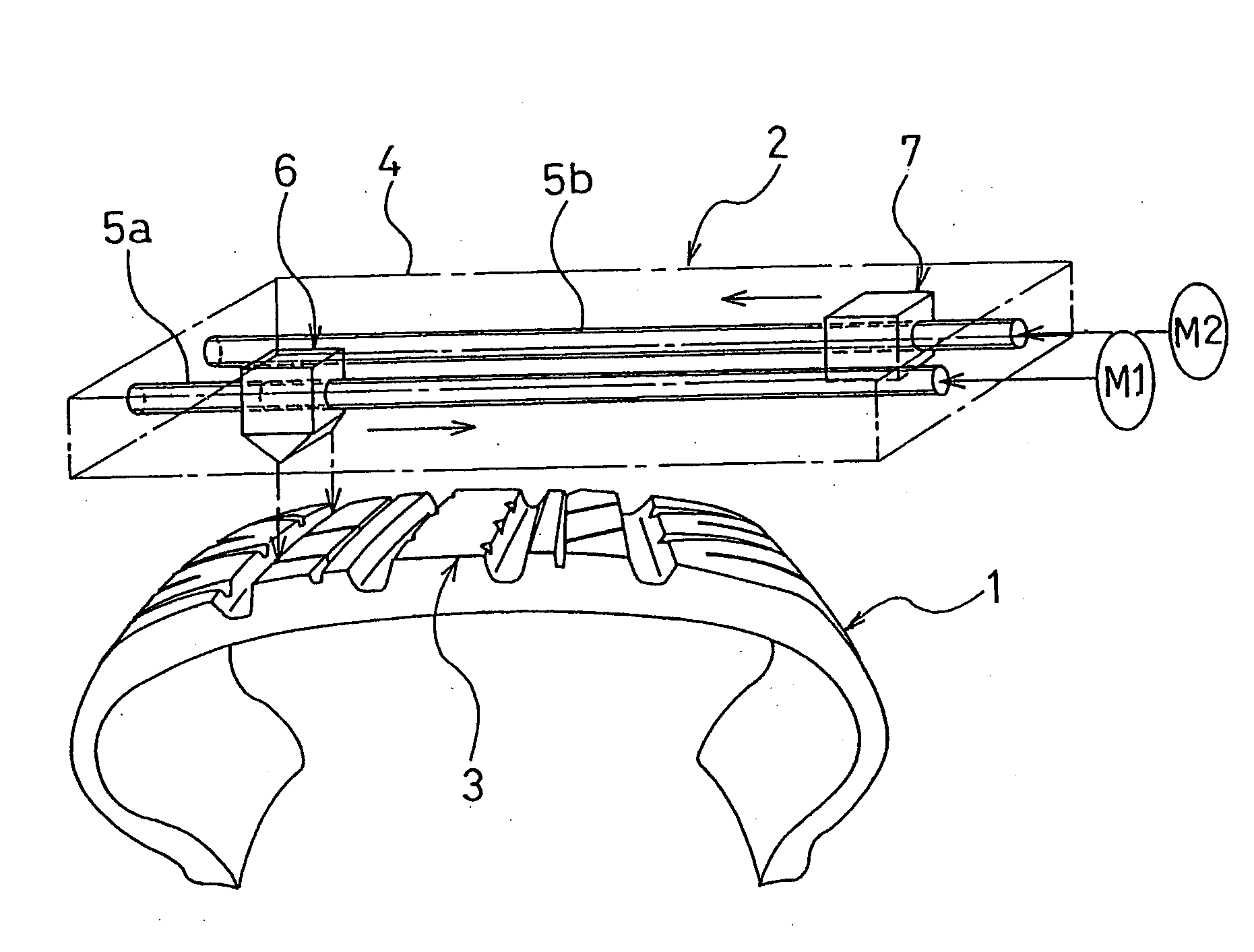
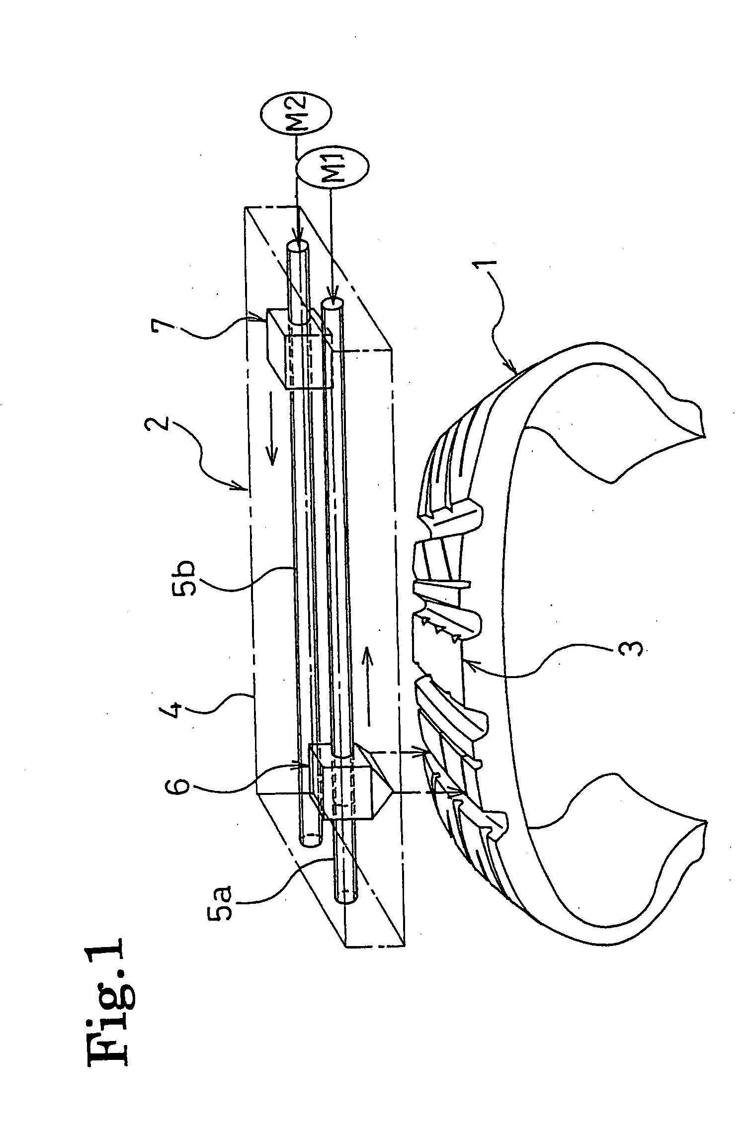
[0016]FIG. 1 shows an apparatus for determining tire shapes according to the present invention. In FIG. 1, the numeral 1 denotes a tire to be measured, and 2 denotes the portable determination apparatus disposed in proximity to a tread portion 3 of the tire 1.

[0017] This determination apparatus 2 has a structure in which two ball screws 5a and 5b are rotatably arranged in parallel with each other in a base member 4 shaped like a box. The ball screw 5a holds an optical displacement gage 6, including a laser light source and a sensor for receiving laser light reflected from a tire surface, so that the optical displacement gage 6 can freely move along a predetermined scanning direction. Meanwhile, the ball screw 5b holds a weight 7, having substantially the same mass as the optical displacement gage 6, so that the weight 7 can freely move along the same scanning direction as that of the optical displacement gage 6. These ball screws 5a and 5b are configured to rotate each in an arbitra...

second embodiment

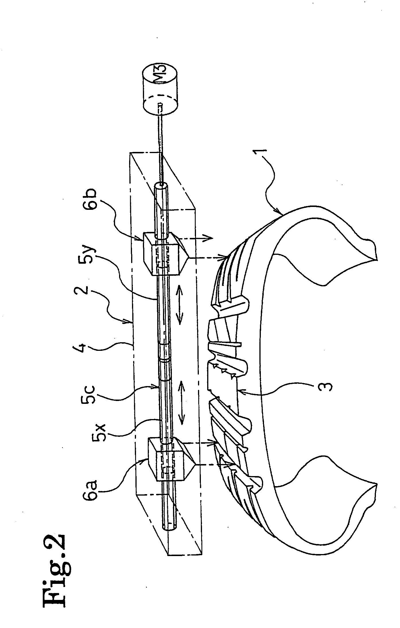
[0023]FIG. 2 shows another apparatus for determining tire shapes according to the present invention. In FIG. 2, a determination apparatus 2 has a structure in which one ball screw 5c is rotatably arranged in a base member 4 shaped like a box. The ball screw 5c holds a pair of optical displacement gages 6a and 6b so that they can move along a predetermined scanning direction. The optical displacement gages 6a and 6b have substantially the same masses and each include a laser light source and a sensor for receiving laser light reflected from a tire surface. More specifically, screw parts 5x and 5y with different thread directions from each other are formed in the ball screw 5c, bordering a central portion of the ball screw 5c in its longitudinal direction. The optical displacement gage 6a is held within a screw part 5x area, while the optical displacement gage 6b is held within a screw part 5y area. The ball screw 5c is configured to rotate in an arbitrary direction, with a servomotor...


PUM


Abstract

A method of and an apparatus for determining tire shapes are provided which enable both an apparatus weight reduction and a determination accuracy improvement. The apparatus of the present invention includes: a portable base member; a non-contact displacement gage held on the base member so as to be freely movable along a predetermined scanning direction; a weight supported on the base member so as to be movable along the scanning direction; and means for symmetrically driving the displacement gage and weight while synchronizing them with each other. Using this apparatus, the method includes: setting the base member in proximity to a tire tread portion so that the displacement gage will scan the tread portion; allowing the displacement gage and weight to symmetrically move along the scanning direction while synchronizing them with each other; and determining the shape of the tread portion, based on an output from the displacement gage.

Description

BACKGROUND OF THE INVENTION [0001] The present invention relates to a method of and an apparatus for determining tire shapes by using a non-contact displacement gage. More specifically, the present invention relates to a method of and an apparatus for determining tire shapes, which enable both a reduction in the weight of the apparatus and an improvement in determination accuracy. [0002] Hitherto, the shapes and groove depths of the tread portion of a pneumatic tire have been determined by using a non-contact displacement gage, and the determination values have been used as data for analyzing tread wear characteristics of the tire or the like. As an apparatus for determining tire shapes as described above, a portable compact determination apparatus has been proposed in which a displacement gage (probe) scans a tire tread portion (for example, see Japanese Unexamined Patent Publication No. H5-256738). [0003] However, in the portable determination apparatus reduced in weight, the weig...

Claims


Application Information

Patent Timeline
Patent Type & Authority Applications(United States)
IPC IPC(8): B60C19/00G01B11/24G01B11/245G01M17/02
CPCG01B11/245G01B11/24
Inventor UEHARA, TSUYOSHI
Owner THE YOKOHAMA RUBBER CO LTD
Why Eureka
Try Eureka