Magnetic tape and maufacturing method thereof, and servo writer and servo write method

a technology of magnetic tape and maufacturing method, applied in the field of magnetic tape, can solve the problems of not being able to identify the position of a data track in a lateral direction of a magnetic tape, and taking time to access each data track,

Active Publication Date: 2005-03-17
FUJIFILM HLDG CORP +1
View PDF9 Cites 112 Cited by
  • Summary
  • Abstract
  • Description
  • Claims
  • Application Information

AI Technical Summary

Benefits of technology

[0008] A first aspect of the present invention for solving the problems described above is a magnetic tape where servo signals for performing tracking-control of a magnetic head are recorded on a plurality of servo bands, wherein a DC (Direct Current) magnetization region magnetized in one direction by direct current is arranged along longitudinal directions of the magnetic tape on each of the

Problems solved by technology

However, when in the method for specifying each servo band by respectively reading servo signals from two servo bands adjacent to both sides of a data band, in a recording/reproducing apparatus, not to mention both sides, a one-side servo read head for reading a servo band causes a read fault of the servo signals due to an unknown r

Method used


Image

  • Magnetic tape and maufacturing method thereof, and servo writer and servo write method
  • Magnetic tape and maufacturing method thereof, and servo writer and servo write method
  • Magnetic tape and maufacturing method thereof, and servo writer and servo write method

Examples


first embodiment

[0036] Next, the magnetic tape MT of the present invention, where the DC magnetization regions LZ1 to LZ5 and the servo signals S1 to S5 are written as above, will be described, referring to FIG. 3A, and FIGS. 4A and 4B.

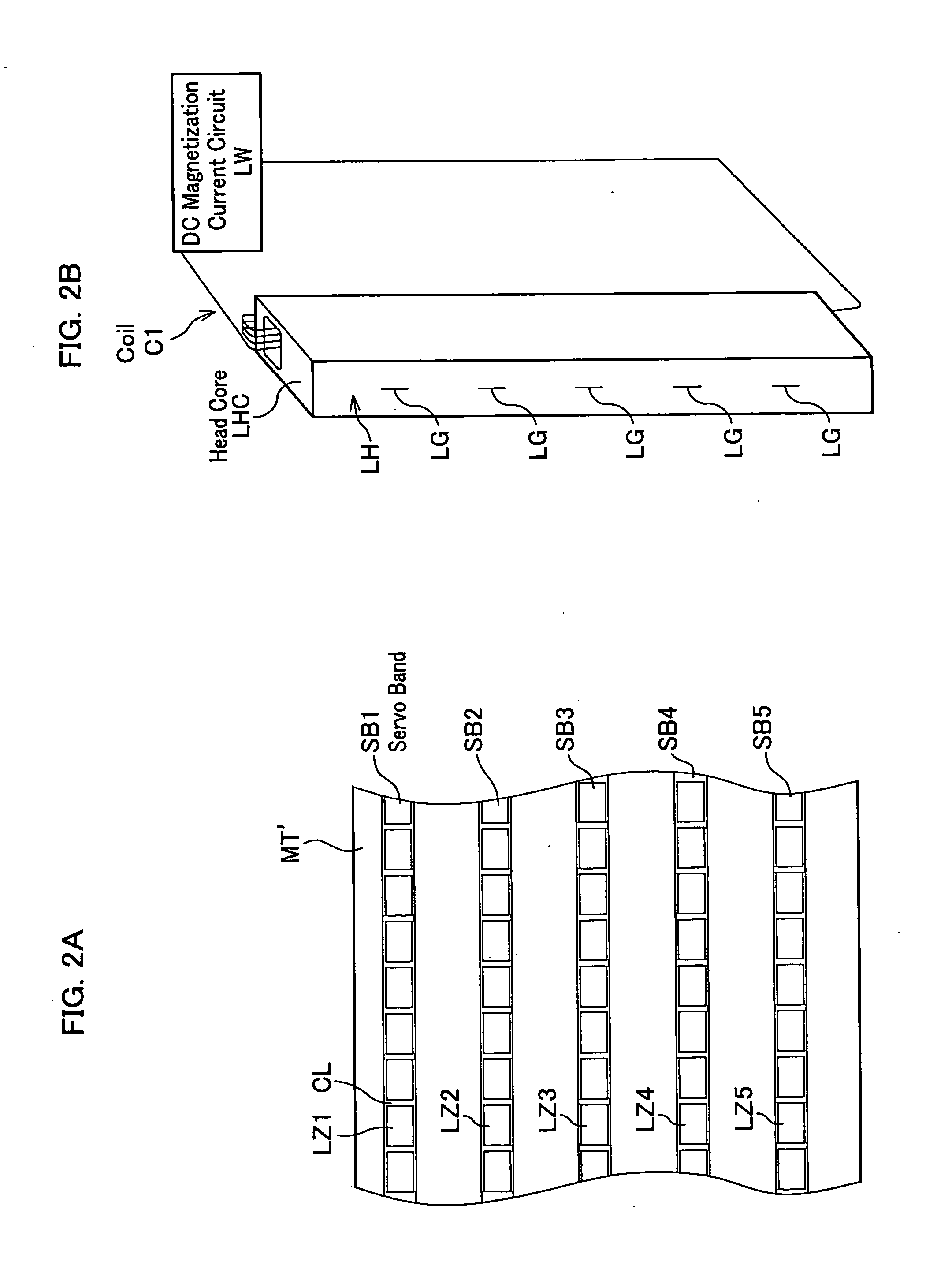
[0037] As shown in FIG. 3A, in the magnetic tape MT along longitudinal directions thereof are provided five servo bands SB1 to SB5 at an equal distance in a lateral direction of the magnetic tape MT, and between these servo bands are provided data bands DB1 to DB4. And on each of the servo bands SB1 to SB5 are, as shown in FIGS. 2A and 3A, formed the DC magnetization regions LZ1 to LZ5 that are discontinuously magnetized in one direction with opening the distance CL. Within each of the DC magnetization regions LZ1 to LZ5 is written each of the predetermined servo signals S1 to S5 for performing tracking-control of a magnetic head.

[0038] The servo signals S1 to S5 are, as in FIG. 4A where nothing but the servo band SB1 is shown in enlargement, configured of sub-frame...

second embodiment

[0041] In addition, FIG. 5A is a drawing showing the magnetization intensity of the DC magnetization regions LZ1 to LZ5 related to the present invention; FIG. 5B is a drawing showing the recording magnetization intensity of servo signals S1 to S5 (linear patterns L1 to L8) of each of the DC magnetization regions LZ1 to LZ5.

[0042] In this magnetic tape along longitudinal directions thereof, same as in the magnetic tape MT related to the first embodiment shown in FIG. 3A, are provided five servo bands SB1 to SB5 at an equal distance in a lateral direction of the magnetic tape, and between these servo bands B1 to B5 are provided the data bands DB1 to DB 4. And on each of the servo bands SB1 to SB5 are, same as in the magnetic tape MT related to the first embodiment shown in FIG. 3A, formed the DC magnetization regions LZ1 to LZ5 that are discontinuously magnetized in one direction with opening the distance CL. It is same as in the magnetic tape MT related to the first embodiment that: ...


PUM


Abstract

A magnetic tape of the present invention comprises a plurality of servo bands and servo signals for performing tracking-control of a magnetic head, wherein the servo signals are recorded on the servo bands, wherein a DC magnetization region magnetized in one direction by direct current is arranged along longitudinal directions of the magnetic tape on the servo bands, wherein each of the servo signals is magnetized in a reverse direction for the one direction of a DC magnetization and is recorded within the DC magnetization region, and wherein any of a relative ratio and relative difference of DC magnetization intensity in the DC magnetization region and recording magnetization intensity of each of the servo signals differs for each of the servo bands.

Description

BACKGROUND OF THE INVENTION [0001] 1. Field of the Invention [0002] The present invention relates to a magnetic tape where a servo signal is written on a servo band and a manufacturing method thereof, and a servo writer and servo write method for writing the servo signal on the magnetic tape. [0003] 2. Description of the Related Art [0004] These years, in a magnetic tape for use in a backup of a computer and the like a high density recording progresses more and more, and in the future the high density recording till around several tens of terabytes is foreseen. Based upon the high density recording, in the magnetic tape a number of data tracks increases, and a width of the data tracks and a distance between adjacent data tracks become narrower. In addition, based upon an augmentation of a memory capacity, the magnetic tape itself becomes a thin layer. Furthermore, in order to handle the increase of the data tracks in the magnetic tape, in a magnetic tape recording / reproducing appara...

Claims


Application Information

Patent Timeline
IPC IPC(8): G11B5/008G11B5/02G11B5/024G11B5/584G11B5/78G11B15/60
CPCG11B5/00813G11B5/02G11B15/60G11B5/584G11B5/78G11B5/024
Inventor OHTSU, HIROKI
Owner FUJIFILM HLDG CORP
Why Eureka
Try Eureka