
Optical information recording medium

a technology of optical information and recording medium, applied in the field of optical information record medium, can solve the problems of inability to avoid the influence of recording frequency etc. in the separation of 2 signals, the above conventional technique is not satisfactory, and the influence of recording frequency etc., so as to reduce the polarization noise

Inactive Publication Date: 2005-03-17
FUJITSU LTD
View PDF11 Cites 15 Cited by
  • Summary
  • Abstract
  • Description
  • Claims
  • Application Information

AI Technical Summary

Benefits of technology

[0023] Another object of the invention is to provide an optical information record medium capable of reducing polarization noises generated by phase pit edges of ROM information in concurrent reading out of ROM-RAM information.

Problems solved by technology

For such an optical information recording medium having the ROM information and the RAM information on the same recording surface, there are many problems for reproducing concurrently the ROM (for reading out only) information consisting of the phase pits PP and the RAM (writable / rewritable) information consisting of Optical Magnetic Memory (OMM).
However, when the degree of the optical intensity modulation is high, the above conventional technique is not satisfactory.
Therefore, it is not easy to form a substrate because it is necessary to form a continuous groove stably and to remove the groove partially.
Therefore, the influence of the recording frequency etc. in separation of 2 signals cannot be avoidable because the main and address information is separated with the frequency bands.
Thus, this technique does not suggest improvement of security because rewriting of a user is not basically prohibited.

Method used


Image

  • Optical information recording medium
  • Optical information recording medium
  • Optical information recording medium

Examples


Embodiment Construction

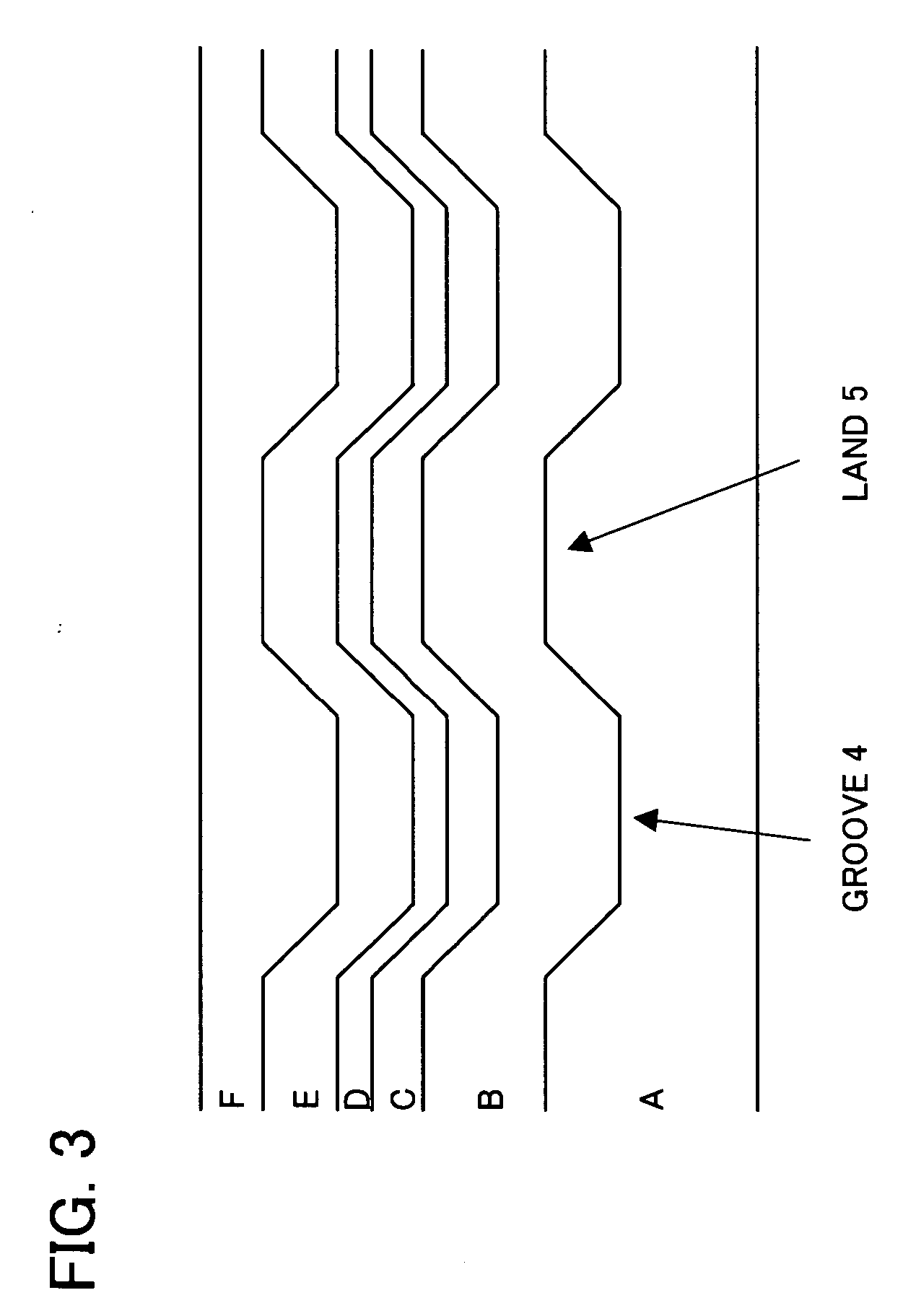
[0080] The cross-sectional shape of a disk optical information recording medium according to the invention is the same as shown in FIG. 3 and FIG. 4, and the same as shown in FIG. 5 in terms of recording of the ROM data and the RAM data for the disk.

[0081] The embodiment of the optical information record medium according to the invention is constituted by forming a dielectric layer B made from SiN etc. on a disk polycarbonate substrate “A” having a diameter of approximately 30-120 mm, then, forming a magneto-optical recording film C made from TbFeCo etc., a dielectric film D and an Al reflecting film E in this order and, finally, applying an overcoat F made from UV-cured resin. In addition, rows of phase pits PP are formed on the optical information record medium as ROM data.

[0082] It is not necessary to form a groove on the magneto-optical recording film C as shown in FIG. 4. However, in order to make the track control more secure for a recording apparatus, it is naturally possib...


PUM


Abstract

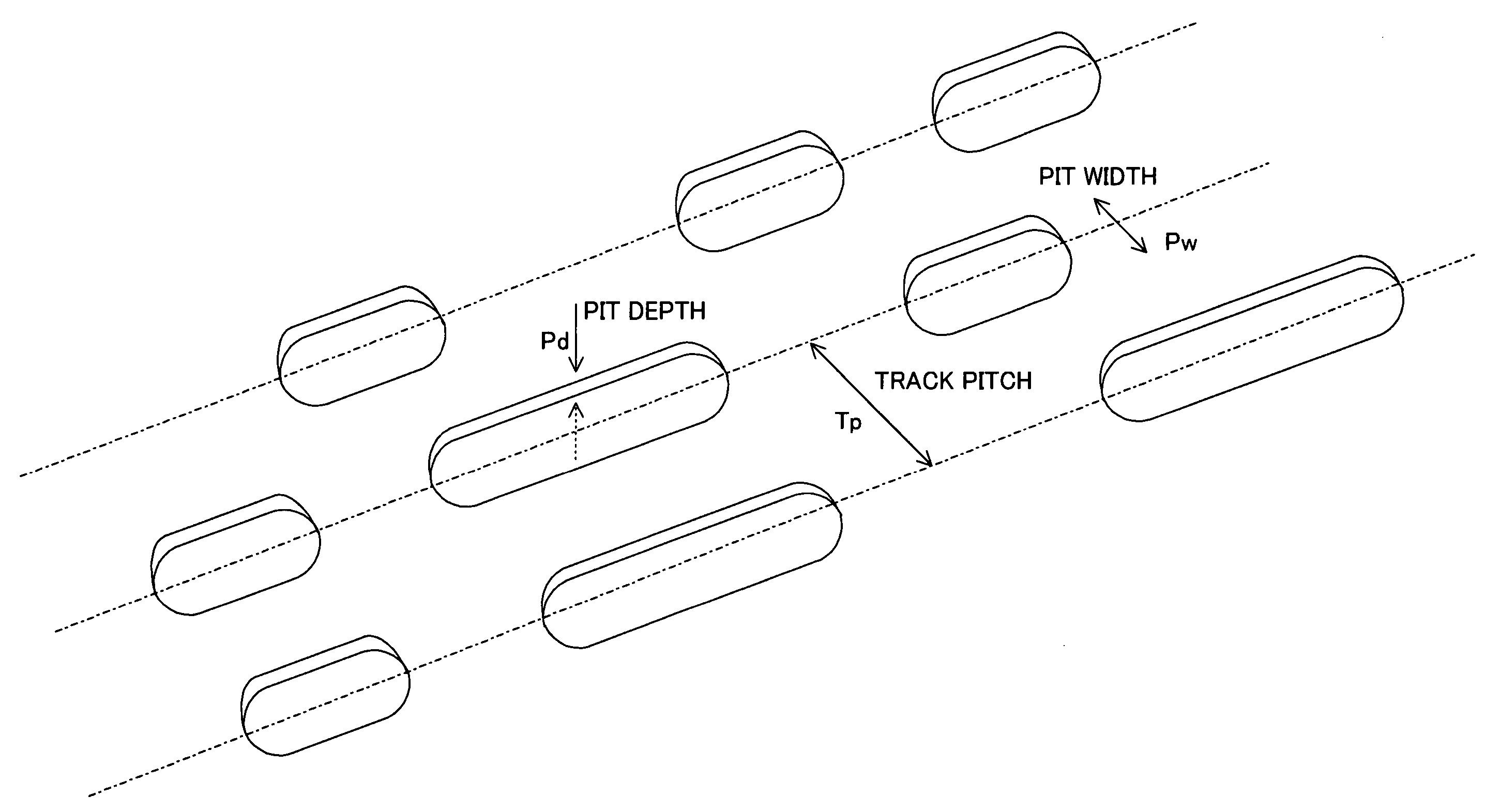
An optical information recording medium can reproduce stably RAM information during concurrent reading out of ROM-RAM information. The optical information recording medium comprises a substrate having a ROM area where phase pits to be ROM data are formed, and a magneto-optical recording film for recording RAM data, formed on an area corresponding to the ROM area of the substrate and, in the ROM area, the degree of modulation in the user area is at least 10-37% and, preferably, the degree of modulation of the phase pits in the user area is 15-25%. As an aspect, the optical depth of the phase pits is approximately λ / 8-λ / 10 (λ is the wavelength of the laser used for recording / reproducing).

Description

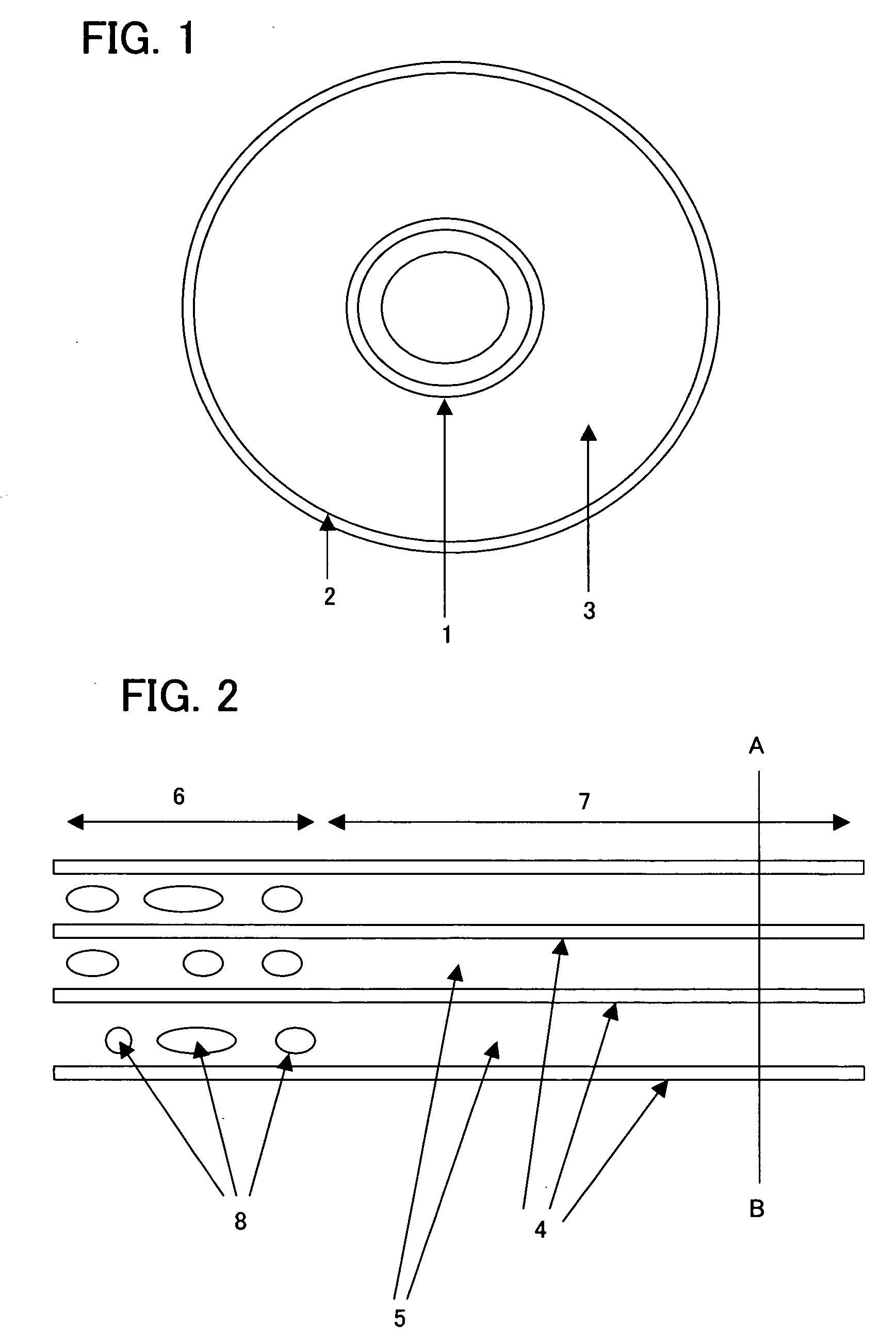
BACKGROUND OF THE INVENTION TECHNICAL FIELD OF THE INVENTION [0001] The present invention relates to an optical information record medium. More particularly, the invention relates to an optical information record medium capable of ROM-RAM concurrent reproduction. PRIOR ART [0002] Today, research and development are being actively advanced in terms of high-density recording / reproducing and high-speed accessing for magneto-optical disk memory. FIG. 1 shows a recording medium conforming with the ISO standard and, more specifically, a plan view of a magneto-optical disk as an example. A read-in 1 and a read-out 2 provide ROM information consisting of phase pits according to a principle that pits and projections formed on a polycarbonate substrate are reflected using a reflection film, and information such as specifications of the disk is recorded in them. An apparatus controls conditions for recording / reproducing by reading the information. [0003] The optical depth (pit depth) of the ph...

Claims


Application Information

Patent Timeline
IPC IPC(8): G11B7/00G11B7/0037G11B7/005G11B7/007G11B7/013G11B7/09G11B7/125G11B7/24G11B7/24038G11B7/24085G11B11/105G11B20/12G11B20/14
CPCG11B7/0052G11B2020/1461G11B7/0079G11B7/126G11B7/24038G11B7/24085G11B11/10528G11B11/10543G11B11/10578G11B11/10584G11B11/10597G11B20/0021G11B20/1217G11B20/1426G11B2007/0013G11B2020/1242G11B2020/1248G11B2020/1274G11B7/00718
Inventor AOYAMA, NOBUHIDEAKIYAMA, RYOTAMORIMOTO, YASUAKIHOSOKAWA, TETSUO
Owner FUJITSU LTD
Learn More