Image coding method and image decoding method

a technology of image coding and decoding method, which is applied in the field of image encoding, can solve the problems of not being able to display pictures after being decoded, not being able to transmit video captured on the tv screen or shot by a tv camera, and not being able to handle the vast information directly in the digital format via the information media mentioned, etc., and achieves a high practicability value

Inactive Publication Date: 2005-03-17
PANASONIC INTELLECTUAL PROPERTY CORP OF AMERICA
View PDF13 Cites 38 Cited by
  • Summary
  • Abstract
  • Description
  • Claims
  • Application Information

AI Technical Summary

Benefits of technology

Thus, according to the present invention, the pictures that can not be displayed correctly in the related art can be displayed by making the most use of the released memory area without having unnecessary memory, therefore, its practical value is high.

Problems solved by technology

Therefore, it is not realistic to handle the vast information directly in the digital format via the information media mentioned above.
For example, a videophone has already been put into practical use via Integrated Services Digital Network (ISDN) with a transmission rate of 64 Kbit / s˜1.5 Mbit / s, however, it is not practical to transmit video captured on the TV screen or shot by a TV camera.
Thus, considering the more flexible combination as a picture encoding type, it is a problem that the pictures which cannot be displayed after being decoded occur.
It is conceivable to add another picture memory for display and store the pictures that are not stored in the picture memory PicMem1 in this picture memory for display so that they can be displayed; however, the weak point is that this picture memory requires a huge memory in this case.
Furthermore, there rises a new problem in the reproduction of a picture in the middle of the stream even if another picture memory for display is introduced. FIG. 2 is a diagram showing a prediction structure, a decoding order and a display order of pictures.
However, Picture 6 is not yet displayed and stored in the picture memory when Picture 7 is decoded, Picture 6 therefore cannot be displayed from the picture memory at its display time if the entire picture memory is initialized before the display of Picture 6 takes place.

Method used


Image

  • Image coding method and image decoding method
  • Image coding method and image decoding method
  • Image coding method and image decoding method

Examples


first embodiment

(First Embodiment)

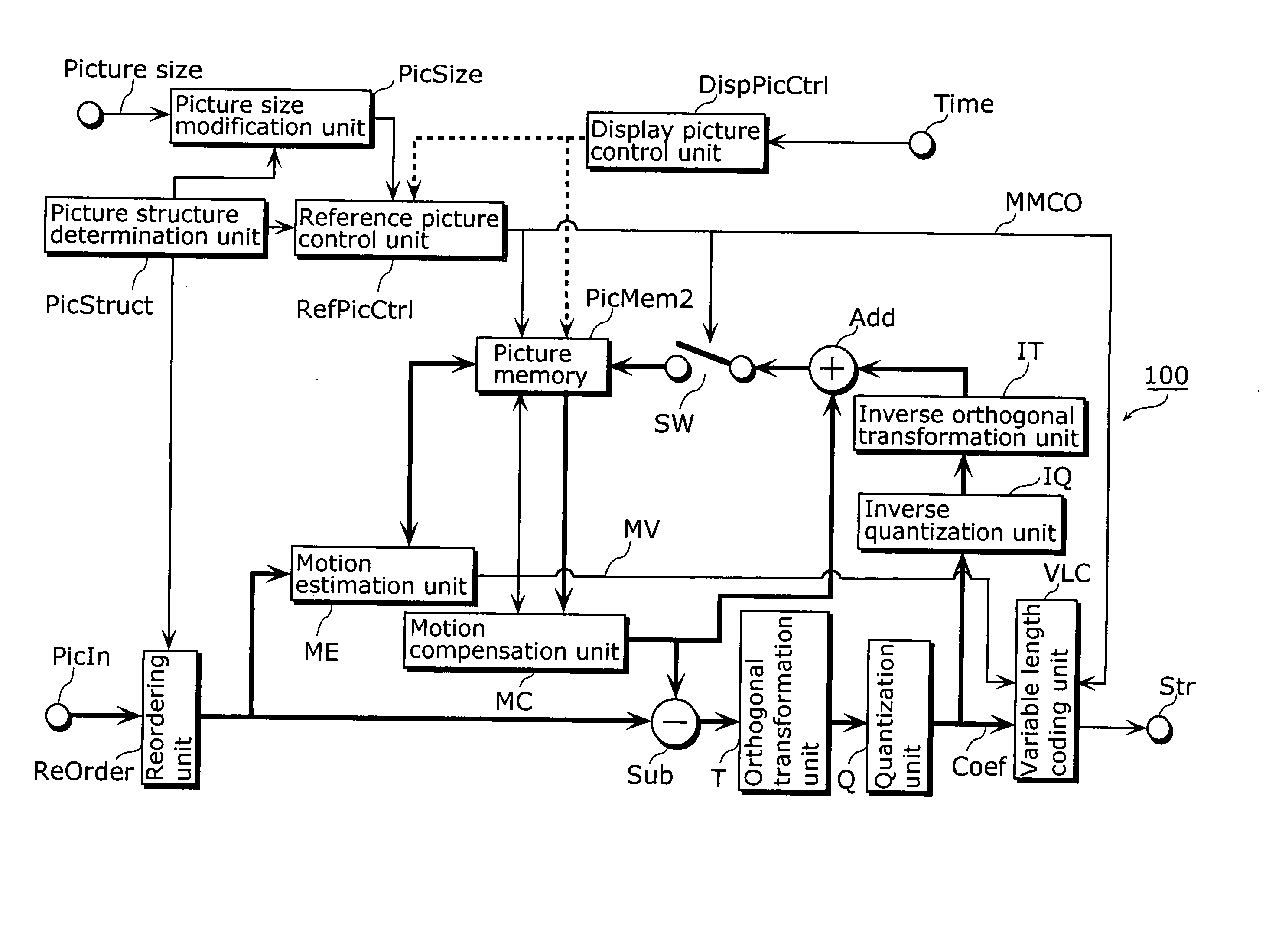
FIG. 3 is a block diagram showing a picture encoding apparatus for realizing a picture encoding method of the present invention. The same referential numbers are put for the devices that operate in the same manner as described in the block showing a picture encoding apparatus for realizing a conventional encoding method shown in FIG. 26 and the explanation is thereby abbreviated.

Differences between the block diagram in FIG. 26 showing the picture encoding apparatus for realizing the conventional picture encoding method and the block diagram in FIG. 3 showing the picture encoding apparatus for realizing the picture encoding method according to the present invention are that a display picture control unit DisPicCtrl is added to FIG. 3 and that instructions sent from the display picture control unit DisPicCtrl are outputted to a reference picture control unit RefPicCtrl and a picture memory PicMem2.

In the picture encoding apparatus 100 shown in FIG. 3, a picture s...

second embodiment

(Second Embodiment)

The following describes a second embodiment of the present invention.

In the present embodiment, the display picture control unit DispPicCtrl shown in FIG. 3 instructs the picture memory PicMem2 not to store a picture newly in the area storing the picture that is not yet displayed, when a picture is stored in the released memory area. Normally, even an area for picture is released, a picture stored right before can be reproduced as long as a picture is not newly stored (overwritten) in the area. Even if a memory area in which the picture that is not yet displayed is released, the picture that is not yet displayed and is released at the time of display but is left without being overwritten can be displayed by storing a picture newly not in the memory area but in the area where the picture that is already displayed is stored. The picture in the released picture area of the picture memory is called picture for display. “Already displayed” here is practically synony...

third embodiment

(Third Embodiment)

The following describes a third embodiment of the present invention.

FIG. 7 is a flowchart of an operation of the picture encoding apparatus 100 of the third embodiment of the present invention. The present embodiment characterizes in determining the storage of the picture according to the time when the memory is released.

Firstly, in Step 30, the picture encoding apparatus 100 judges whether or not the decoded picture is to be stored in the picture memory PicMem2 based on the instruction indicated in the memory control command MMCO.

In the case of storing the decoded picture in the picture memory, the released picture memory area whose display time is the earliest within released area is obtained (Step 31) and the decoded picture is stored in the obtained area (Step 32).

The memory area in which the picture is decoded and stored at the earliest time instead of the memory area released at the earliest display time may be allocated as an area to store the pictur...


PUM


Abstract

A picture encoding method of the present invention is a picture encoding method of predictively encoding an input picture with reference to pictures stored in a picture buffer, decoding the encoded input picture, judging whether or not the decoded picture is a picture for reference and whether or not the decoded picture is a picture for output which needs to be stored until its display time, and storing, in the picture buffer, the picture for reference and the picture for output based on the determination result.

Description

TECHNICAL FIELD The present invention relates to a picture encoding method for compressing efficiently a moving picture and a picture decoding method for decoding correctly the encoded picture and displaying it. BACKGROUND ART Recently, with an arrival of the age of multimedia which handles integrally audio, video and pixel values of others, existing information media, i.e., newspapers, journals, TVs, radios and telephones and other means through which information is conveyed to people, has come under the scope of multimedia. Generally speaking, multimedia refers to something that is represented by associating not only with characters but also with graphics, audio and especially pictures and the like together. However, in order to include the aforementioned existing information media in the scope of multimedia, it appears as a prerequisite to represent such information in digital form. However, when calculating the amount of information contained in each of the aforementioned inf...

Claims


Application Information

Patent Timeline
Patent Type & Authority Applications(United States)
IPC IPC(8): H04N19/105G06T9/00H04N19/114H04N19/134H04N19/136H04N19/152H04N19/159H04N19/196H04N19/423H04N19/426H04N19/46H04N19/50H04N19/503H04N19/60H04N19/61H04N19/70H04N19/895H04N19/91H04N21/234H04N21/44
CPCH04N21/23406H04N21/44004H04N19/00569H04N19/50H04N19/70H04N19/577H04N19/61H04N19/44H04N19/423H04N19/55H04N19/51H04N19/105G06T1/60G06T7/20G09G5/18G09G2360/12H04N19/126H04N19/52
Inventor LIM, CHONG SOONFOO, TECK WEESHEN, SHENG MEIKADONO, SHINYAKONDO, SATOSHIHAGAI, MAKOTOABE, KIYOFUMI
Owner PANASONIC INTELLECTUAL PROPERTY CORP OF AMERICA
Why Eureka
Try Eureka