
Copy-forgery-inhibited pattern density parameter determination method, copy-forgery-inhibited pattern image generation method, and image processing apparatus

a pattern density and parameter determination technology, applied in the field of copyforgery-inhibited pattern density parameter determination, copyforgery-inhibited pattern image generation method, image processing apparatus, can solve the problems of inability to reproduce small dots perfectly on the copy, the copying machine suffers a limitation on image reproduction performance, etc., and achieve the effect of efficient determination of copyforgery-inhibited pattern density parameters

Inactive Publication Date: 2005-03-17
CANON KK
View PDF27 Cites 86 Cited by
  • Summary
  • Abstract
  • Description
  • Claims
  • Application Information

AI Technical Summary

Benefits of technology

It is an object of the present invention to efficiently determine copy-forgery-inhibited pattern density parameters which are used to optimally determine the print densities of a latent-image part and background-image part and are required to generate a copy-forgery-inhibited pattern image in which the latent-image and background-image parts have approximate print densities and the background-image part disappears after copying, even when the halftone reproduction characteristics of the latent-image and background-image parts are different due to the printer engine characteristics, output paper characteristics, individual differences, and the like, and density variations due to a print environment and aging are large in the on-demand copy-forgery-inhibited pattern output method by a printer.

Problems solved by technology

Such special pattern is generally called a “copy-forgery-inhibited pattern”, which applies a mechanism that does not allow an original to be readily copied, thus psychologically inhibiting a copy of an original.
In general, a copying machine suffers a limitation on image reproduction performance depending on the input resolution upon reading small dots of a document to be copied or the output resolution upon reproducing small dots.
Therefore, when a document includes isolated small dots beyond the limitation on the image reproduction performance of the copying machine, these small dots cannot be perfectly reproduced on its copy, and the isolated small dots disappear.
That is, when the background-image part of the copy-forgery-inhibited pattern is designed to exceed the limitation of dots that can be reproduced by the copying machine, large dots (concentrated dots) of the copy-forgery-inhibited pattern can be reproduced by copying, but small dots (scattered dots) cannot be reproduced.
Since the aforementioned copy-inhibition paper sheets are prepared by pre-printing a copy-forgery-inhibited pattern on dedicated sheets by a print paper vendor, they have demerits in terms of cost such as cost produced upon using dedicated sheets, cost produced upon preparing pre-print sheets more than necessary, and the like.
However, some printers have largely different halftone reproduction characteristics of the latent-image and background-image parts due to the printer engine characteristics and individual differences.
For example, in case of a laser printer, the electric field distribution of a photosensitive drum is susceptible to changes in the humidity and temperature.
When the electric field distribution becomes broad and smooth, reproduction of scattered dots or isolated dots becomes unstable.
However, upon finding out optimal copy-forgery-inhibited pattern density parameters in consideration of changes in densities of the latent-image and background-image parts depending on the print environment, aging, and the like, if a density change width produced as a result of a change in print environment or aging is also considered, a large number of combinations of copy-forgery-inhibited pattern density parameters are prepared by dividing a relative broad range from lower to higher densities in increments of a change width as slight as the density difference between the latent-image and background-image parts cannot be visually recognized, and undergo a test printing process, so as to find out optimal copy-forgery-inhibited pattern density parameters.
It is possible to execute test printing processes of all copy-forgery-inhibited pattern density parameters, but many paper sheets are wasted by the test printing processes.
Therefore, in a printer which has unknown halftone reproduction characteristics of the latent-image and background-image parts depending on its engine characteristics or output paper sheets (e.g., a printer of an old generation or a printer in the future), or a printer which suffers a large density change of the latent-image and background-image parts depending on the print environment, aging, and the like, it is difficult to obtain an optimal copy-forgery-inhibited pattern image by a single test printing process.
For this reason, in the on-demand copy-forgery-inhibited pattern output method by a printer, printers that can output a copy-forgery-inhibited pattern image are limited.
However, in case of the above implementation, at the density of a copy-forgery-inhibited pattern selected by the creator of the copy-forgery-inhibited pattern from the user interface, the background may not disappear upon copying due to too high a density, or parameters at which a latent-image emerges upon copying may not be found due to too low a density.
Therefore, the sequence for finding out optimal copy-forgery-inhibited pattern parameters is troublesome for the creator of the copy-forgery-inhibited pattern.

Method used


Image

  • Copy-forgery-inhibited pattern density parameter determination method, copy-forgery-inhibited pattern image generation method, and image processing apparatus
  • Copy-forgery-inhibited pattern density parameter determination method, copy-forgery-inhibited pattern image generation method, and image processing apparatus
  • Copy-forgery-inhibited pattern density parameter determination method, copy-forgery-inhibited pattern image generation method, and image processing apparatus

Examples


first embodiment

[First Embodiment]

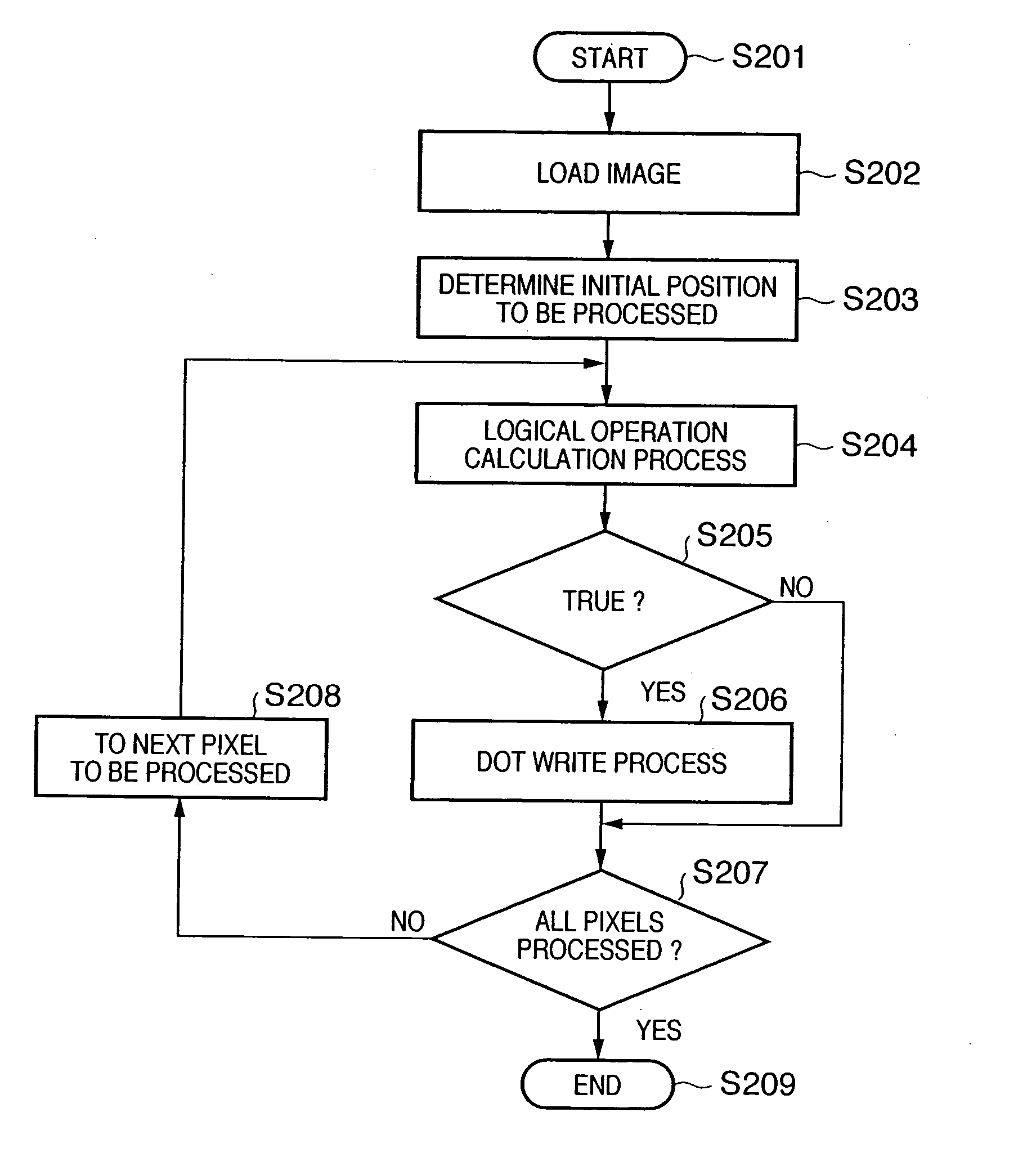
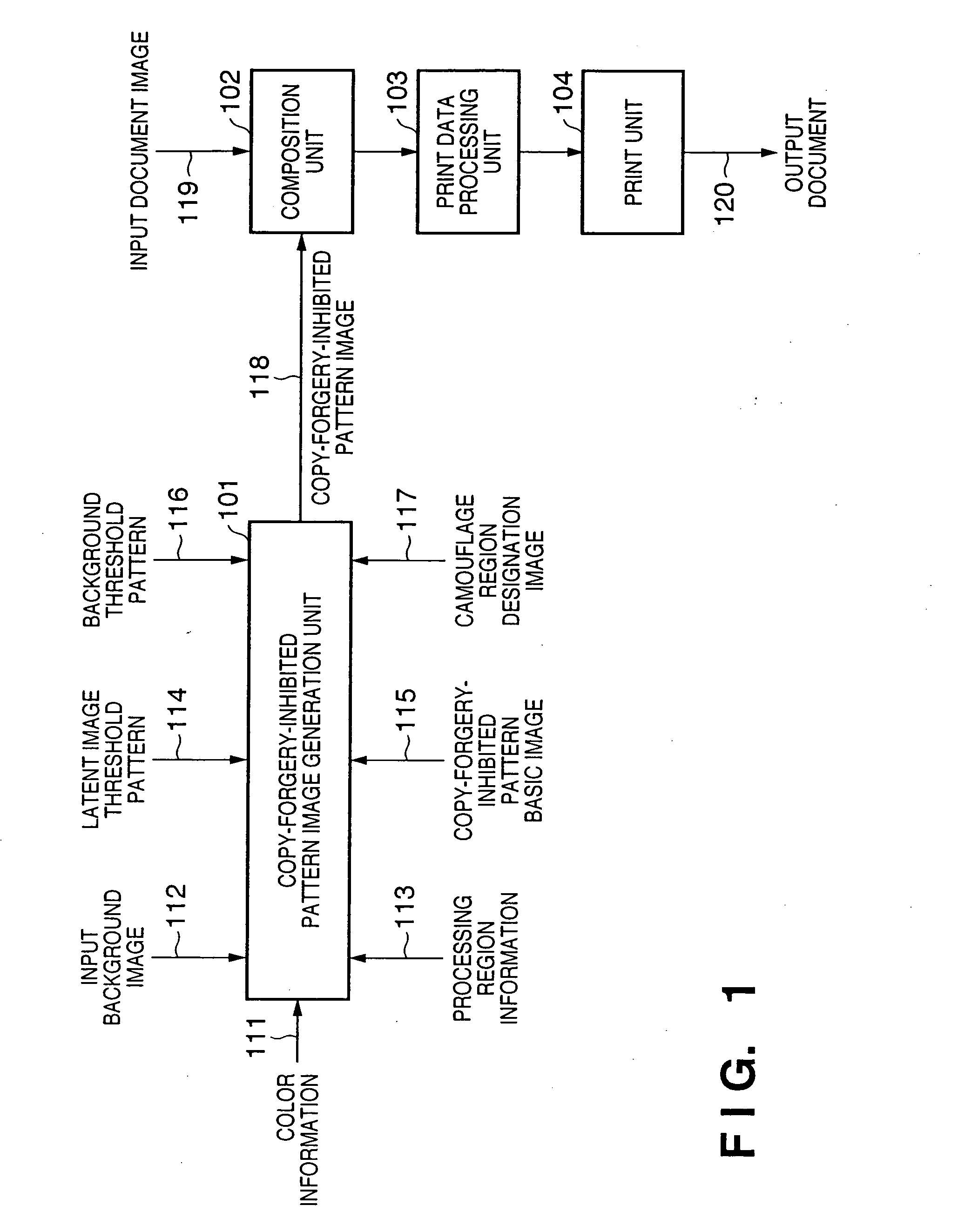
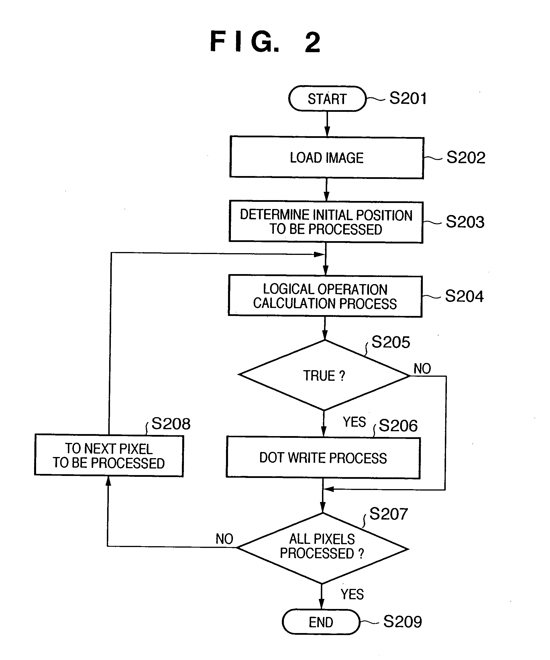
In this embodiment, a combination of a background threshold pattern and latent-image threshold pattern as patterns (binary images) which form the background-image part and latent-image part and can set equal densities for the background-image part and latent-image part upon printing is determined in advance, and logical operations are executed using the background threshold pattern, the latent-image threshold pattern, a copy-forgery-inhibited pattern basic image as a binary image that designates the latent-image part and background-image part, and a camouflage region designation image as a binary image that designates a camouflage region, thereby generating a copy-forgery-inhibited pattern image at high speed using a small memory size.

Note that the background threshold pattern and latent-image threshold pattern are parameters that determine the densities of the background-image part and latent-image part of a copy-forgery-inhibited pattern image upon printing, a...

second embodiment

[Second Embodiment]

The second embodiment according to the present invention will be described in detail hereinafter with reference to the accompanying drawings. In the second embodiment, respective processes described in the first embodiment are implemented by a computer.

FIG. 25 is a block diagram showing the basic arrangement of a computer in the second embodiment. For example, when this computer executes all the functions except for the print unit (or the printer engine of the print unit) in FIGS. 1, 15, 22, and 23 in the first embodiment, the respective functions are expressed by a program, which is loaded by this computer, thus implementing all the functions except for the print unit (or the printer engine of the print unit) in FIGS. 1, 15, 22, and 23 in the first embodiment.

Referring to FIG. 25, reference numeral 2511 denotes a CPU which controls the overall computer, and executes respective processes described in the first embodiment using programs and data stored in a RAM...


PUM


Abstract

A primary test printing process of a plurality of copy-forgery-inhibited pattern images generated by changing one or both of print densities of the latent-image and background-image parts in a first pattern on the basis of a predetermined parameter is performed. The user selects one copy-forgery-inhibited pattern image which has the latent-image and background-image parts with approximate print densities from the plurality of copy-forgery-inhibited pattern images generated by the primary test printing process. A secondary test printing process of a plurality of copy-forgery-inhibited pattern images generated by changing one or both of print densities of the latent-image and background-image parts in a second pattern on the basis of the parameter used to determine the print densities of the latent-image and background-image parts of the selected copy-forgery-inhibited pattern image is performed. The user selects one copy-forgery-inhibited pattern image which has the latent-image and background-image parts with approximate print densities from the plurality of copy-forgery-inhibited pattern images generated by the secondary test printing process, and the parameter of the selected copy-forgery-inhibited pattern image is determined as a copy-forgery-inhibited pattern density parameter.

Description

FIELD OF THE INVENTION The present invention relates to a technique for compositing a copy-forgery-inhibited pattern on the background of a document, and outputting a composite document for the purpose of inhibiting illicit forgery and information leakage due to copies of important documents. BACKGROUND OF THE INVENTION On some receipts, securities, and certificates, a special pattern which emerges as a character string or image when they are copied is printed on the background, so as to prevent them from being readily copied. Such special pattern is generally called a “copy-forgery-inhibited pattern”, which applies a mechanism that does not allow an original to be readily copied, thus psychologically inhibiting a copy of an original. This copy-forgery-inhibited pattern is formed of two regions, i.e., a region where dots remain after copying and a region where dots disappear after copying. These two regions have substantially the same densities, and a hidden character string or i...

Claims


Application Information

Patent Timeline
Patent Type & Authority Applications(United States)
IPC IPC(8): G03G21/00G03G21/04
CPCH04N1/00883G03G21/043Y10S283/902
Inventor MURAKAMI, TOMOCHIKA
Owner CANON KK
Learn More