Electrical connector having reduced variation range of characteristic impedance

Inactive Publication Date: 2005-03-17
HON HAI PRECISION IND CO LTD
View PDF3 Cites 24 Cited by
  • Summary
  • Abstract
  • Description
  • Claims
  • Application Information

AI Technical Summary

Benefits of technology

[0008] Accordingly, an object of the present invention is to provide a mini DVI electrical connector that can decrease va

Problems solved by technology

If a small impedance is connected to a big impedance, that is impedance mismatch, then the power that can pass through the connection is limited by the larger impedance.
In general, impedance mismatch in a transmission path causes signal reflection, which leads to signal losses such as reduction in signal amplitude, cancellation of certain signals, and so on.
Furthermore, part si

Method used


Image

  • Electrical connector having reduced variation range of characteristic impedance
  • Electrical connector having reduced variation range of characteristic impedance
  • Electrical connector having reduced variation range of characteristic impedance

Examples


Embodiment Construction

[0018] Reference will now be made in detail to the preferred embodiment of the present invention.

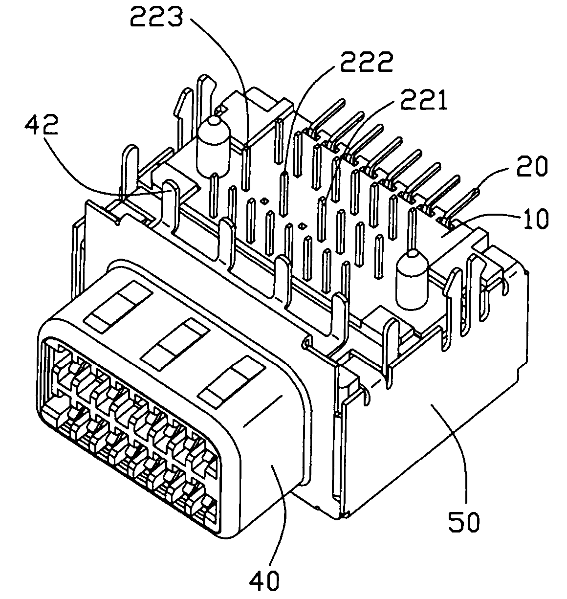
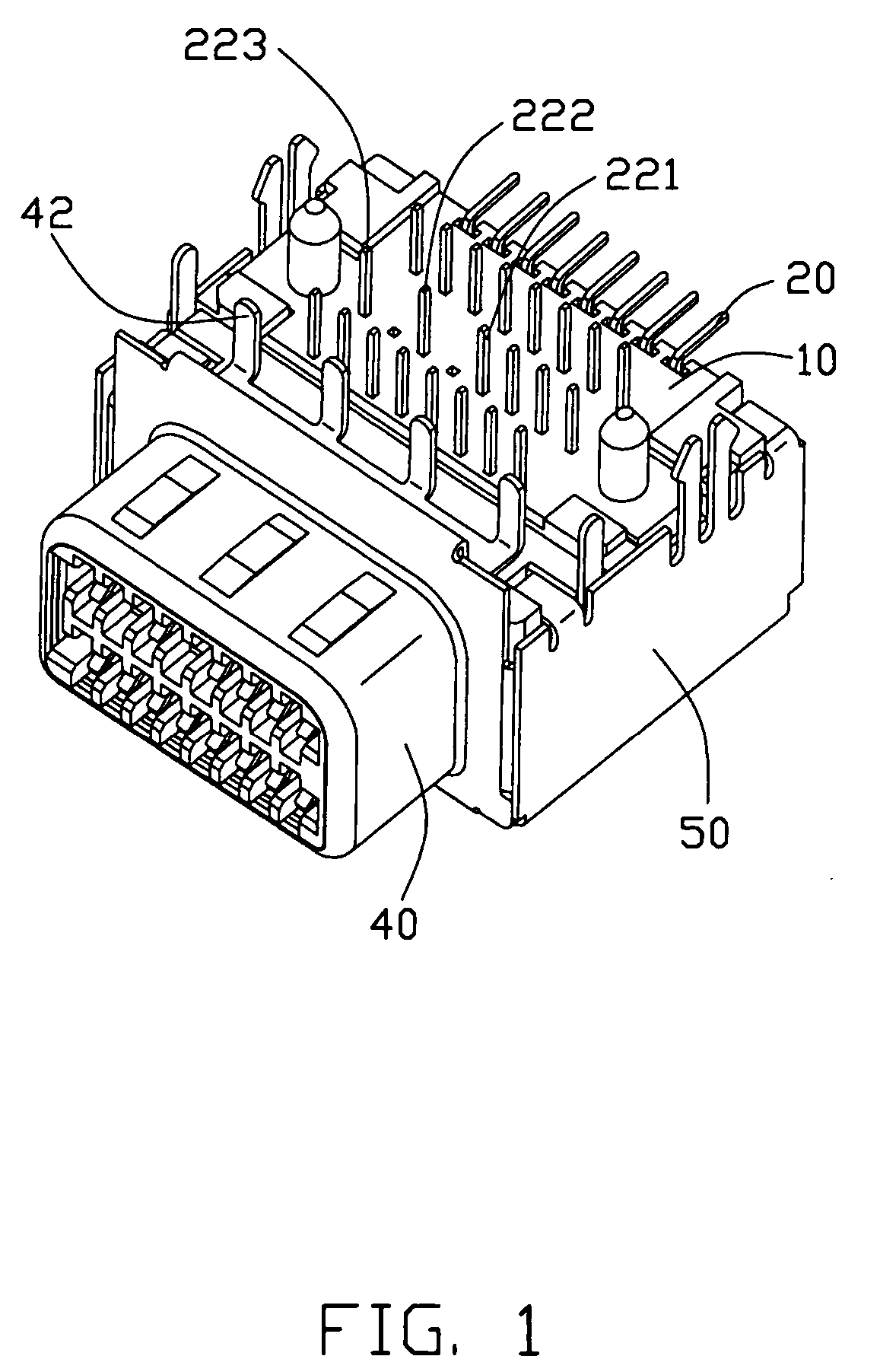
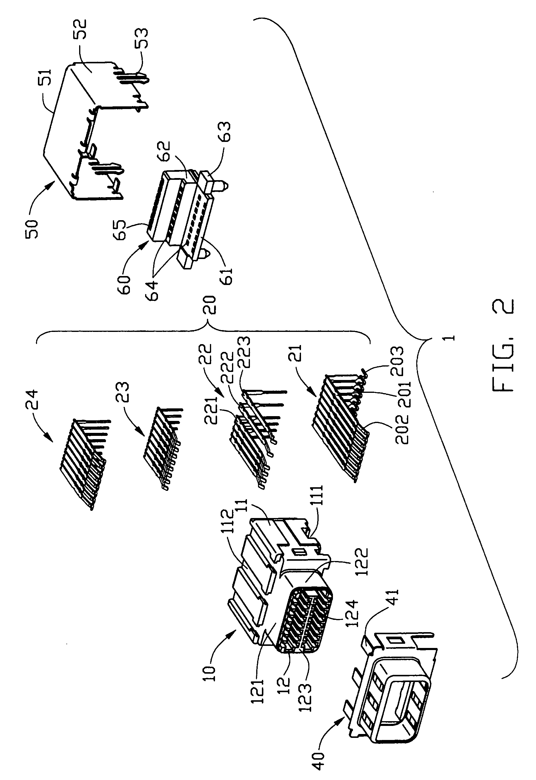
[0019] Referring to FIG. 1 and FIG. 2, a mini DVI electrical connector 1 in accordance with the present invention for transmitting visual signal comprises an insulative housing 10, a plurality of conductive terminals 20 received in the insulative housing 10, a pair of shielding shells 40, 50 enclosing the insulative housing 10 and a spacer 60 assembled at a rear portion of the insulative housing 10 for positioning the conductive terminals 20 therein.

[0020] The insulative housing 10 comprises a body portion 11 and a mating portion 12 extending forwardly from the body portion 11. The mating portion 12 has an upper wall, a lower wall 121 and a pair of side walls 122 connecting with the upper and lower walls 121. The mating portion 12 has a tongue 123 extending between the two side walls 122 and parallel to the upper and lower walls 121. A plurality of passageways 124 are respectively defi...


PUM


Abstract

An electrical connector (1) includes an insulative housing (10), a number of terminals (20) and a shielding shell. The housing includes a body portion, (11), a mating portion (12) extending forwardly from the body portion and a number of passageways (124) defined therein. The terminals includes a number of digital signal, power, grounding and analog signal terminals (221, 222, 223). The terminals have four groups (21, 22, 23, 24) arrayed in rows. The group (22) of terminals includes three analog signal terminals. The distance between the adjacent two analog signal terminals is twice the distance between adjacent two other types of terminals except the analog signal terminals, thereby reducing variation range of characteristic impedance of the connector.

Description

BACKGROUND OF THE INVENTION [0001] 1. Field of the Invention [0002] The present invention is related to an electrical connector, and more particularly to a Mini Digital Visual Interface (MDVI or Mini DVI) electrical connector mounted onto a printed circuit board. [0003] 2. Description of Related Art [0004] With the rapid development of today's electronic products, transfer rate and data storage capacity of the electronic products are increased to a great extent. In such high frequency and high-speed electronic equipments, it is desirable that all electronic components of an interconnection path be optimized for signal transmission characteristics, otherwise the signal integrity of the system will be impaired or degraded. Obviously high frequency characteristics of the electronic components, such as risetime degradation or system bandwidth, crosstalk, impedance control and propagation delay, play a significant role in signal transmission. When transmitting high-speed data signals thr...

Claims


Application Information

Patent Timeline
IPC IPC(8): H01R12/04H01R12/55H01R13/40H01R13/60H01R13/648
CPCH01R12/724H01R13/6581H01R13/6477
Inventor WANG, ZHENSHENG
Owner HON HAI PRECISION IND CO LTD
Why Eureka
Try Eureka