
Cut-resistant composite

Inactive Publication Date: 2005-03-17
DYNATEX
View PDF9 Cites 22 Cited by
  • Summary
  • Abstract
  • Description
  • Claims
  • Application Information

AI Technical Summary

Benefits of technology

[0012] By providing an insulating layer between the fabric and the matrix, the present invention provides a composite and / or a fabric wherein the reinforcement elements in the fabric and / or composite will not act as individual elements but will act as a “group” or a “set” of elements. A major advantage of the reinforcement yarns or elements to act as a set of elements is that different elements are able to simultaneously undergo some displacement, when acting upon by a cutting element. As a consequence, individual elements will less easily be cut through, and cutting resistance of the fabric will be greatly improved. The present invention thus provides a composite having maximal cutting resistance, by enabling the anti-cutting or anti-vandalism reinforcement elements to act as free as possible, i.e. by creating “bundles” or “groups” of individual elements before a single element gets cut through.
[0014] The presence of free spaces or cavities between the individual elements of the fabric considerably improves the ability of the individual elements acting as a group or bundle of individual elements to undergo some movement or displacement, when acting upon by a cutting element and thus again greatly improves the cutting resistance of the composite.
[0017] In another embodiment, the invention provides a composite, which comprises a cut-warning fabric. In accordance with the present invention, the alarm system may be either activated upon a) interruption / cutting off or closure of an electrical circuit provided in the fabric, or b) providing a contact between a positive and a neutral or negative electrical circuit provided in the fabric. One possibility is that the layer of reinforcement elements is acting as a circuit. As soon as one end is cut, the electrical circuit is broken and an alarm goes on. Such type of composite is particularly suitable for preventing acts of vandalism performed with non-conductive, e.g. ceramic cutting elements. Another possibility is that one layer of reinforcement elements is acting as a positive conductor and another layer is acting as a negative or neutral conductor, such that connection between both layers induces an alarm signal. Such type of composite is particularly suitable for preventing acts of vandalism performed with conductive cutting elements.
[0018] In a third aspect, the present invention provides a method for preventing vandalism on a composite by activating an alarm signal when the composite is subjected to acts of vandalism, e.g. cut through. The alarm system may be activated when someone tries to cut or cuts through the composite. In accordance with the present invention, the alarm system may be activated upon providing a contact between a positive and a neutral or negative electrical circuit (i.e. the insulating layers or the reinforcement elements) provided in the composite according to the present invention.

Problems solved by technology

These last constructions have as major difficulty, i.e. the stiffness and the weight.
The first “loop” knit construction has as major difficulty when it is used as “anti-hooligan” fabric in seats of trains, trams, busses, it may, upon damage pierce and stick through the fabric.
So even if it helps a lot to improve cut resistance in the fabric, the seat can no more be used as the metal will pinch through the skin of the user as well.
A major difficulty of the existing fabrics and / or composites is that the fabric reinforcing elements, e.g. yarns, fibers, cables, once embedded and thus connected to a matrix, are acting as individual elements during cutting or perforation.
As a consequence, the reinforcement elements which act as individual elements can be more easily cut through and will not provide sufficient cutting resistance to the fabric or composite.

Method used


Image

  • Cut-resistant composite
  • Cut-resistant composite
  • Cut-resistant composite

Examples


examples

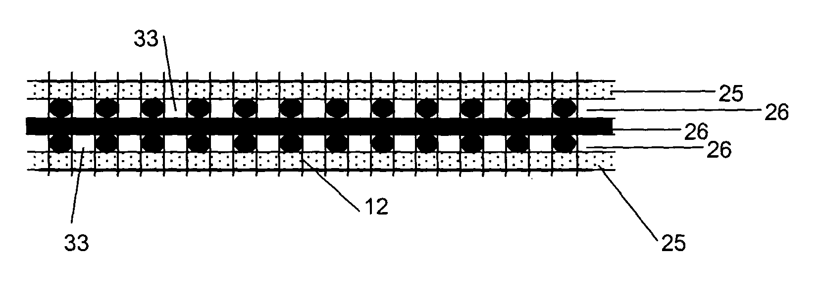
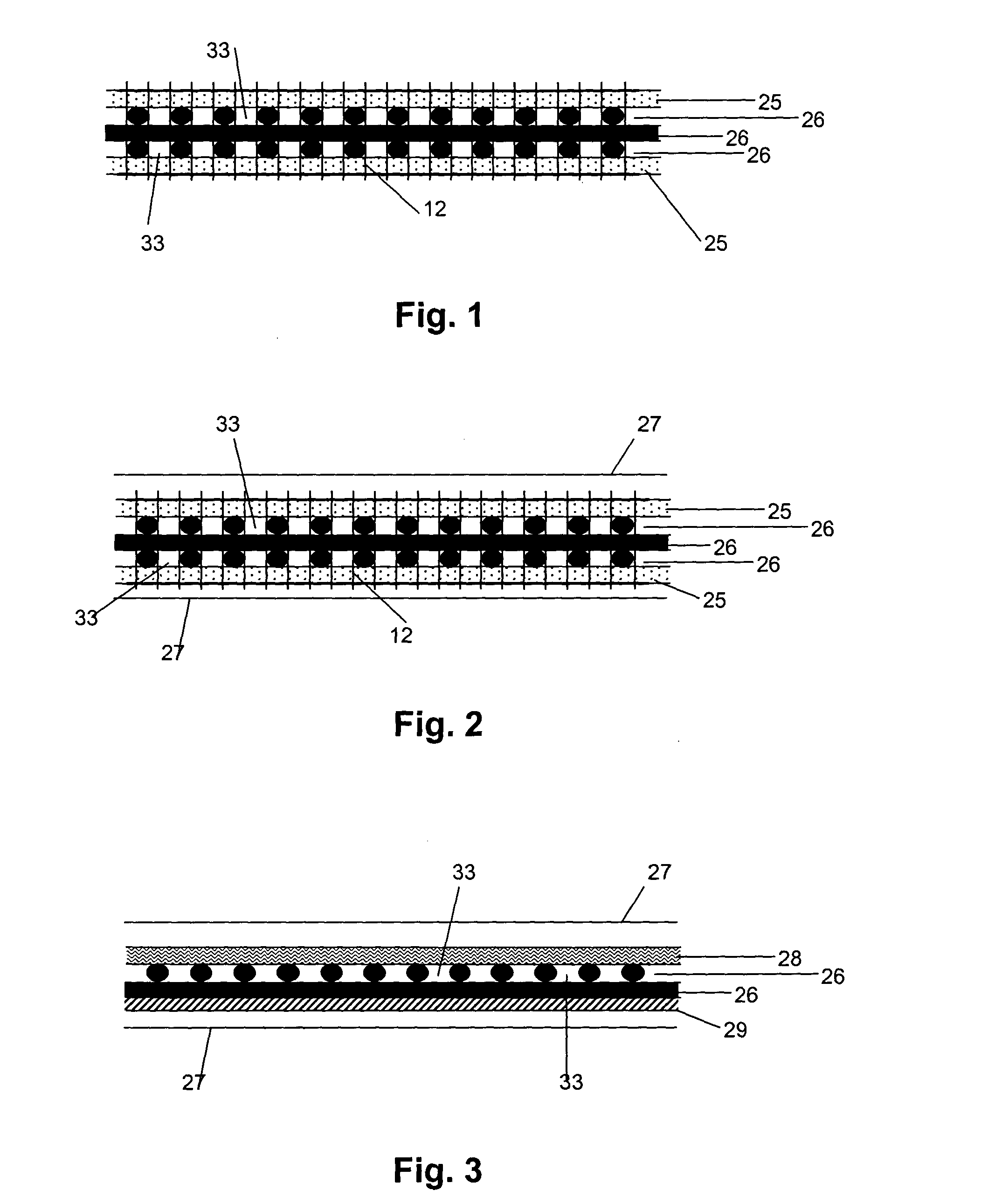
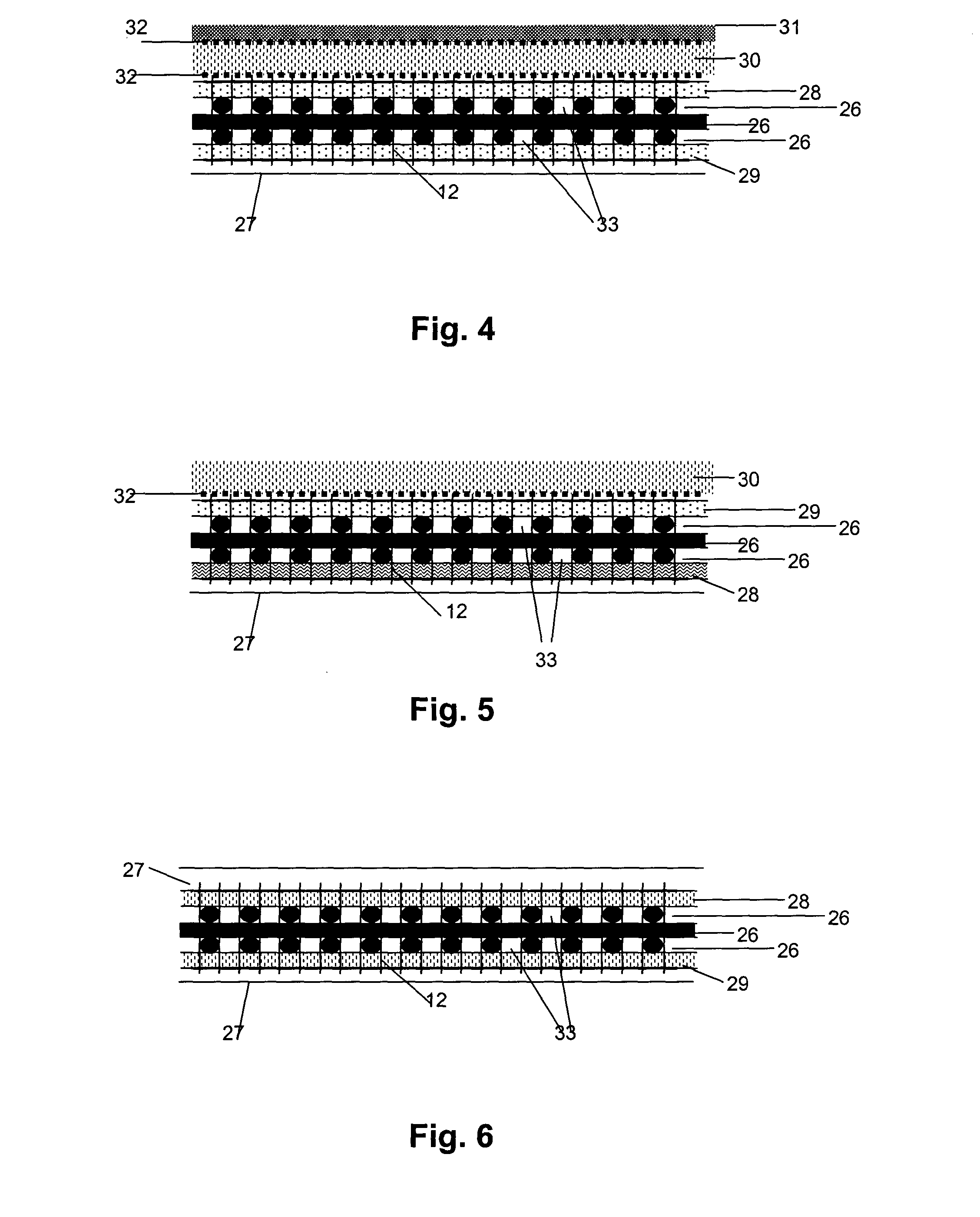
[0146] In a first example, a composite according to the present invention is represented in FIG. 1. The composite comprises a matrix (not represented), three layers of individual elements (e.g. metal yarns) 26 which are provided on their outside surface with an insulating layer 25, in particular a non-woven. Further represented is a knitted connection thread 12, interconnecting the insulating layer 25 and the layers of individual metal yarns 26. The figure further represents the free spaces 33, provided between the individual elements in the layers of individual elements 26.

[0147] FIGS. 2 to 9 represent other embodiments of a composite according to the present invention comprising insulating layers, a fabric and a matrix.

[0148] In FIG. 2 the composite comprises three layers of individual yarns 26, e.g. steel yarns having a diameter of 0.175 mm, which are provided on their outside surface with non woven insulating layers 25. The non-woven layers 25 are provided between the yarns an...


PUM

PropertyMeasurementUnit
Fractionaaaaaaaaaa
Fractionaaaaaaaaaa
Fractionaaaaaaaaaa

Abstract

The present invention relates in a first aspect to a cut-resistant and / or cut-warning composite comprising a matrix, provided on one side of a fabric, a fabric, and at least one insulating layer provided between said matrix and said fabric. In another aspect, the invention relates to a composite, whereby cavities are provided between the individual elements of said fabric. In another aspect, the present invention relates to a method for preventing vandalism on a composite. In another aspect, the invention relates to the use of a composite according to the present invention as an anti-vandalism composite.

Description

FIELD OF THE INVENTION [0001] The present invention relates to the field of cut-resistant composites and cut-resistant fabrics. In a first aspect, the present invention relates to a cut-resistant composite. In another aspect, the present invention relates to a cut-warning composite. In yet another aspect the present invention relates to a method for preventing vandalism on a composite. In another aspect, the invention relates to the use of a composite according to the present invention as an anti-vandalism composite. BACKGROUND OF THE INVENTION [0002] In order to prevent thefts, recently researches have been done to obtain cut resistant materials and constructions. This has already a lot of applications, especially in thermoharding materials. There are also known types of reinforcements for thermoplastic materials as e.g. a knitted “loop” fabric based on a knitted metal loop reinforcement. Also a woven tarpaulin reinforcement is already known comprising woven and knitted steel const...

Claims


Application Information

Patent Timeline
IPC IPC(8): A41D31/00B32B5/02B32B5/08B32B5/12B32B5/26B60R25/10D02G3/44F41H5/04
CPCA41D31/0061B32B5/02B32B5/08B32B5/12B32B5/22F41H5/0478B32B15/02B60R25/1004B60R2325/304D02G3/442D10B2505/18B32B5/26D04B21/165D10B2403/02412D10B2403/0122A41D31/245Y10T442/2139Y10T442/3382Y10T442/2615Y10T442/138Y10T442/109Y10T442/188B32B25/10B32B7/12B32B27/12B32B7/06B32B2307/202B32B15/14B32B5/04B32B2307/206B32B2307/581
Inventor MOESEKE, MARC VAN
Owner DYNATEX
Learn More