Spinal column implant

Inactive Publication Date: 2005-03-17
AESCULAP AG
View PDF187 Cites 280 Cited by
  • Summary
  • Abstract
  • Description
  • Claims
  • Application Information

AI Technical Summary

Benefits of technology

[0033] In addition, the pressure in the piston and cylinder unit can now be relieved, and it is advantageous for this purpose if the adjusting means has a pressure relief valve.
[0034] Provisions are made in a preferred embodiment for at least one of the contact surfaces to be connected with the adjusting means by a detachable connection, especially an elastic locking or snap-in connection. It is possible as a result to intraoperatively equip a certain adjusting means with different contact surfaces, for examp

Problems solved by technology

The contact surfaces thus frequently correspond to the area of the vertebral body surfaces, and it may therefore be difficult to introduce these spinal column implants into the body.
This prevents minimally invasive access and also makes it difficult to pass through the implant between bone parts of t

Method used


Image

  • Spinal column implant
  • Spinal column implant
  • Spinal column implant

Examples


Embodiment Construction

[0076] Although the invention is illustrated and described herein with reference to specific embodiments, the invention is not intended to be limited to the details shown. Rather, various modifications may be made in the details within the scope and range of equivalents of the claims and without departing from the invention.

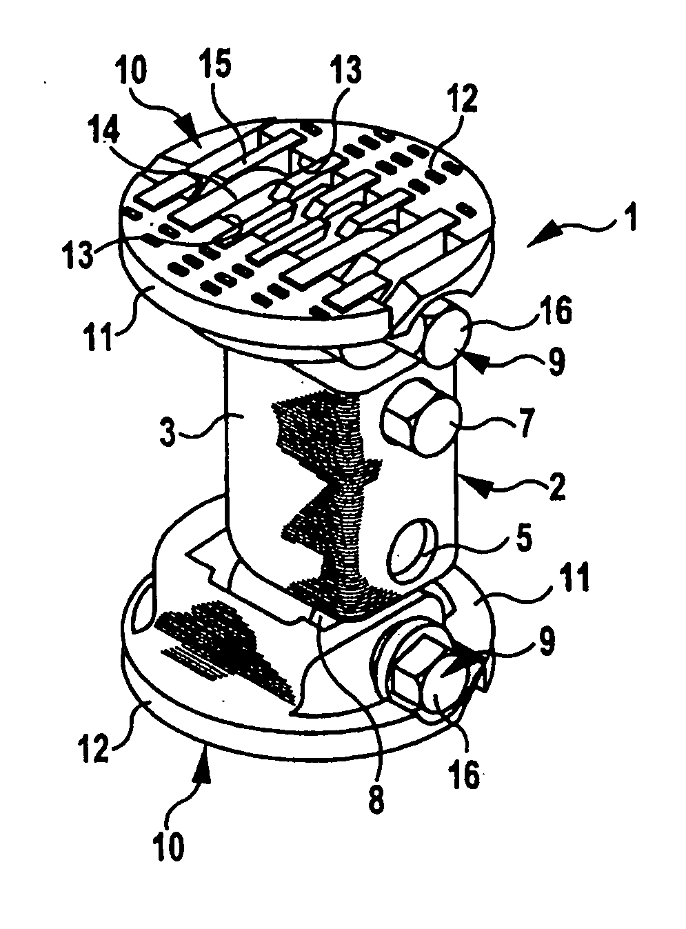
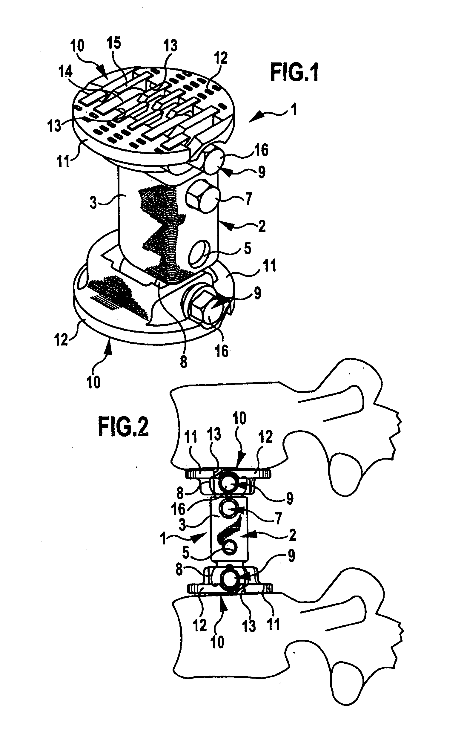
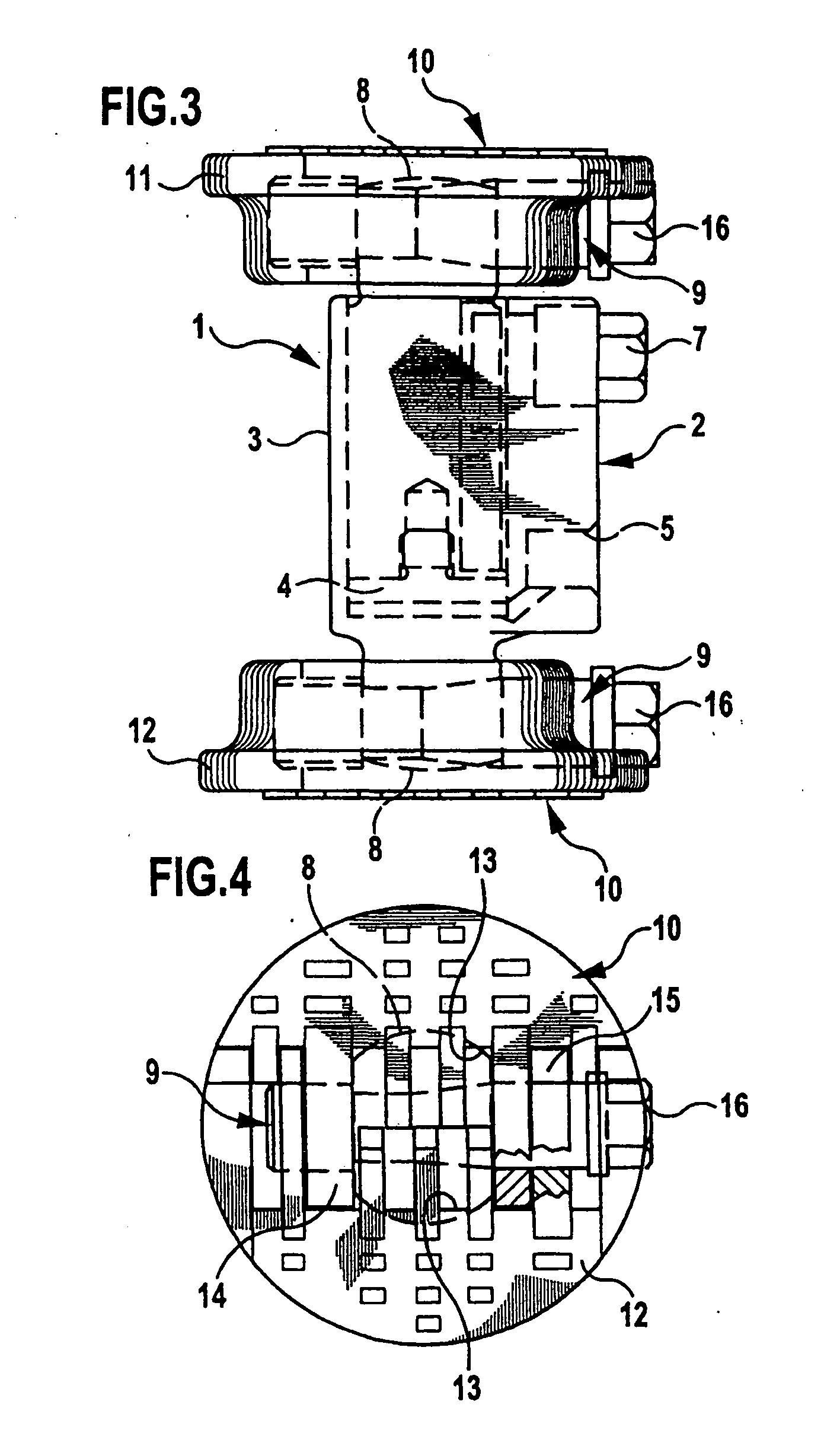
[0077] The implants shown in FIGS. 1 through 23 are vertebral body replacement implants and those in FIGS. 24 through 30 are intervertebral implants.

[0078] The implant 1 shown in FIGS. 1 through 5 comprises a piston and cylinder unit 2 with a cylinder 3 and a piston 4 mounted displaceably therein. The interior space of the piston and cylinder unit 2 can be connected via a connection opening 5 with a flexible tube 6, and this flexible tube 6 is in connection with an external reserve of a pressurizing medium (not shown), for example, a syringe-like instrument, with which a hydraulic medium, e.g., a saline solution or even a compressed gas, can be introduced into ...


PUM

PropertyMeasurementUnit
Fractionaaaaaaaaaa
Angleaaaaaaaaaa
Lengthaaaaaaaaaa

Abstract

A spinal column implant is provided for contact with a vertebral body. The implant includes at least one contact surface including a contact plane having a cross-sectional area in contact with the vertebral body. The shape and arrangement of the at least one contact surface is adjustable such that the cross-sectional area of the contact plane is larger in a contact position than in an insertion position.

Description

[0001] This application is related to and claims the benefit of German Utility Model No. 203 11 400.0 entitled Spinal Column Implant issued on Oct. 2, 2003, and German Patent Application No. 103 33 659.1 filed Jul. 24, 2003. FIELD OF THE INVENTION [0002] The present invention pertains to intervertebral and vertebral implants, with which the original height of the intervertebral disk or vertebral body can be restored in case of, e.g., degeneratively altered intervertebral disks or vertebral bodies. BACKGROUND OF THE INVENTION [0003] Spinal column implants can be inserted in an intervertebral space in order to replace a removed intervertebral disk and thus to support two directly adjacent vertebral bodies against one another, either by a rigid connection or by an articulated connection. In such a case, the spinal column implants are in contact as flat implants with their contact surfaces on the front sides of the adjacent vertebral bodies. [0004] However, spinal column implants of thi...

Claims


Application Information

Patent Timeline
IPC IPC(8): A61F2/00A61F2/02A61F2/30A61F2/44
CPCA61F2/44A61F2310/00179A61F2/4425A61F2002/30131A61F2002/30187A61F2002/30365A61F2002/30369A61F2002/30395A61F2002/30405A61F2002/30471A61F2002/305A61F2002/30507A61F2002/30525A61F2002/30538A61F2002/3055A61F2002/30571A61F2002/30579A61F2002/30584A61F2002/30604A61F2002/30616A61F2002/30841A61F2002/30878A61F2002/30879A61F2002/30884A61F2002/484A61F2220/0025A61F2220/0033A61F2220/0091A61F2230/0013A61F2230/0034A61F2250/0006A61F2/441A61F2/484
Inventor SCHULTZ, ROBERTBEGER, JENSLINDNER, STEPHANSCHUMACHER, JORGKRAMER, ULRICHBADER, UWEWALLSTEIN, STEFAN
Owner AESCULAP AG
Why Eureka
Try Eureka