Method and apparatus of monitoring temperature and strain by using fiber bragg grating (FBG) sensors

a technology of fiber bragg grating and temperature and strain, which is applied in the direction of heat measurement, force measurement by measuring optical property variation, instruments, etc., can solve the problems of limiting the use of these sensors to a few hours, failure of various components, and further coating

Inactive Publication Date: 2005-03-24
SIEMENS AG
View PDF12 Cites 60 Cited by
  • Summary
  • Abstract
  • Description
  • Claims
  • Application Information

AI Technical Summary

Problems solved by technology

Such high temperatures can cause failure of various components unless they are protected from the heat.
The surface then heats up in that regions which weakens the superalloy body and causes further spalling o

Method used


Image

  • Method and apparatus of monitoring temperature and strain by using fiber bragg grating (FBG) sensors
  • Method and apparatus of monitoring temperature and strain by using fiber bragg grating (FBG) sensors
  • Method and apparatus of monitoring temperature and strain by using fiber bragg grating (FBG) sensors

Examples


Embodiment Construction

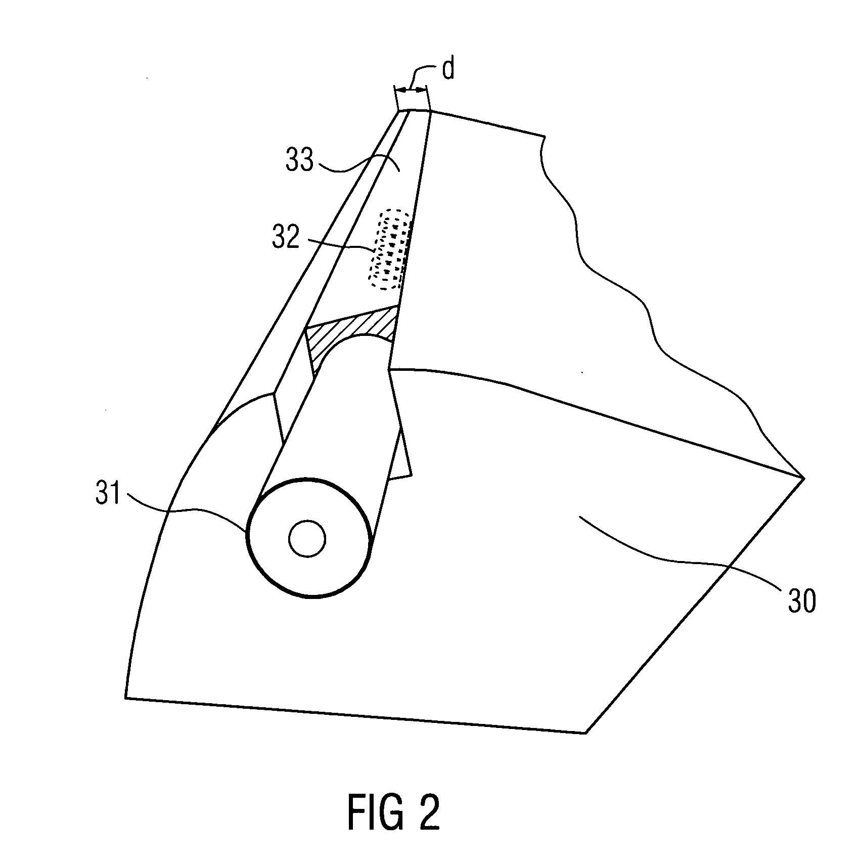
[0016] A concept of the present invention is the use of high temperature resistant fiber Bragg gratings (FBG) for the measurement of temperature distributions and the measurement of strain inside of turbines. Another concept is the durable real-time or near real-time monitoring of temperature and strain in ceramic thermal barrier coatings (TBC).

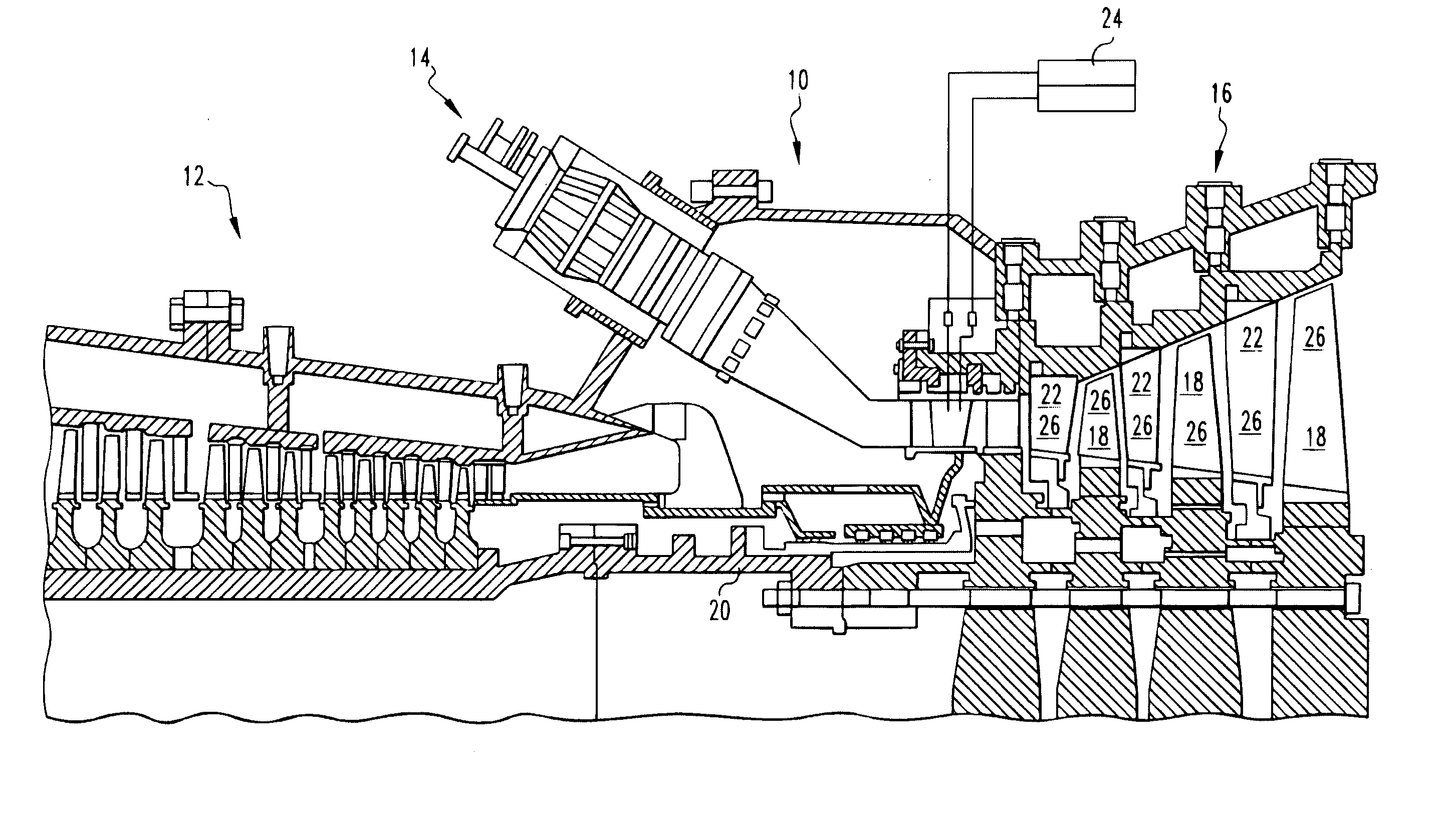
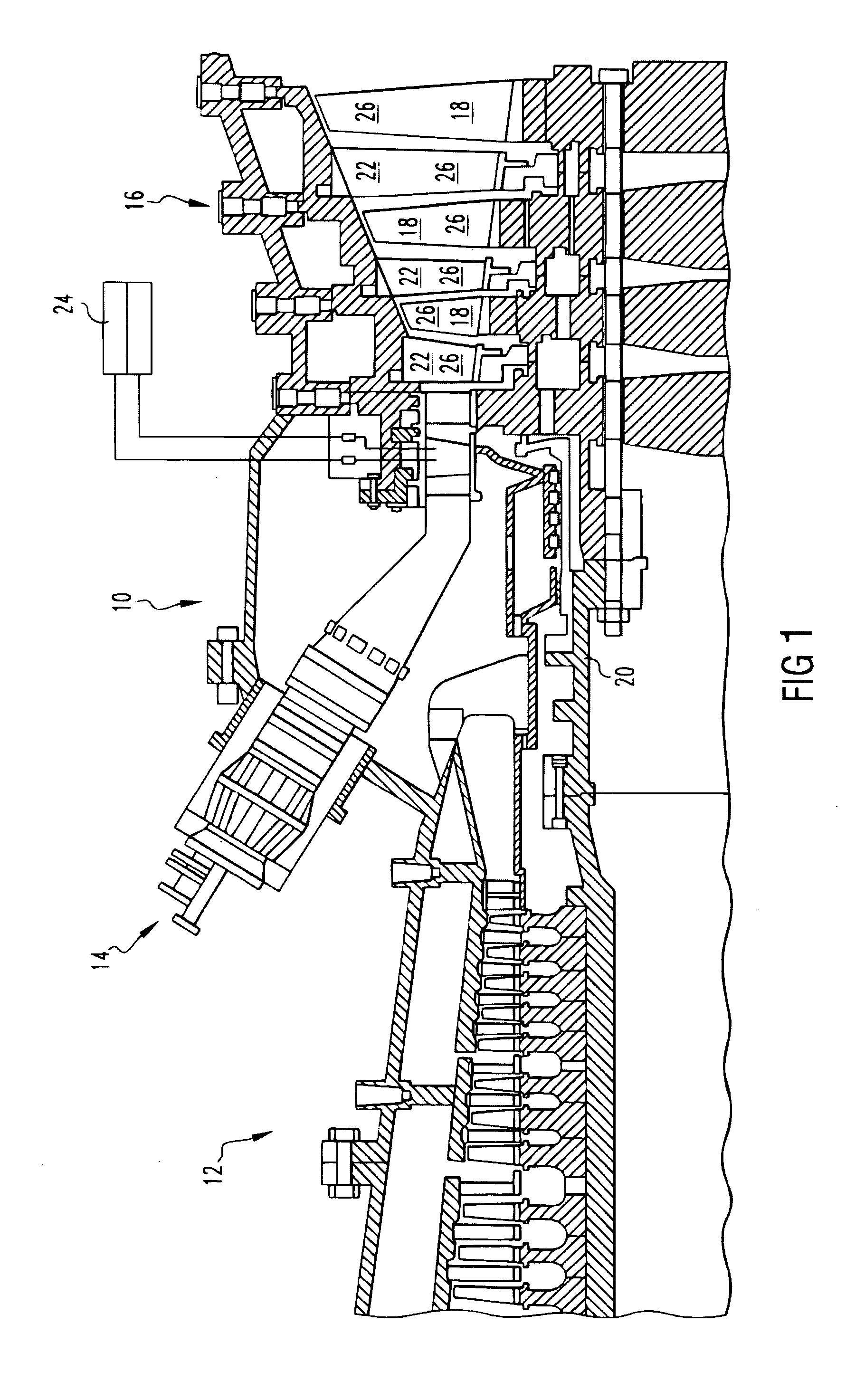
[0017] A preferred embodiment of the invention is a method and a system for monitoring of the condition of exposed high temperature components within a combustion turbine. The invention is particularly useful for monitoring the condition of the thermal barrier coating covering vanes and blades within the turbine. The significance and functioning of the present invention are best understood through a description of the environment within a combustion turbine.

[0018]FIG. 1 illustrates a combustion turbine 10. The combustion turbine 10 includes a compressor 12, at least one combustor 14, and a turbine 16. The turbine 16 includes a plurality of ...


PUM


Abstract

A method and apparatus for monitoring changes in temperature or strain, using fiber Bragg gratings (FBG). The Method and apparatus is advantageously useful for the measurement under harsh conditions, such as by combustion turbines. The invention uses the wavelength shift which is caused by temperature or strain changes at the FBG and the changing of the refraction index of the fiber.

Description

CROSS REFERENCE TO RELATED APPLICATIONS [0001] This application claims the benefits of the provisional U.S. application 60 / 505,700 filed Sep. 24, 2003.FIELD OF THE INVENTION [0002] The invention generally relates to a method and an apparatus of monitoring temperature and strain using fiber Bragg grating (FBG) sensors. More specifically, the invention relates to a method and an apparatus of monitoring temperature and strain of a metal component within a steam or combustion turbine using fiber Bragg grating (FBG) sensors. BACKGROUND OF THE INVENTION [0003] Steam or combustion turbines typically operate at extremely high temperatures, for example, 1500° F. to 2000° F. for steam turbines, respective 2500° F. to 2900° F. (1371° C. to 1593° C.) for gas turbines. Such high temperatures can cause failure of various components unless they are protected from the heat. These components include the rotating blades of the turbine, and the vanes for directing gas flow within the turbine. A typica...

Claims


Application Information

Patent Timeline
IPC IPC(8): G01K11/32G01L1/24
CPCG01L1/246G01K11/32
Inventor WILLSCH, MICHAELBOSSELMANN, THOMASSANJANA, ZALTHEUNE, NILS
Owner SIEMENS AG
Why Eureka
Try Eureka