Method and apparatus for scanning feet for the purpose of manufacturing orthotics and other footwear

Inactive Publication Date: 2005-03-24
FOOT LEVELERS
View PDF6 Cites 53 Cited by
  • Summary
  • Abstract
  • Description
  • Claims
  • Application Information

AI Technical Summary

Benefits of technology

[0007] It is an object of this invention to provide a novel method and apparatus for obtaining foot measurements for the making of corrective footwear such as arch supports, orthotics, and

Problems solved by technology

The present methods of producing an image of a foot require a significant amount of material and equipment in terms of volume and mass.
Additionally, the ca

Method used


Image

  • Method and apparatus for scanning feet for the purpose of manufacturing orthotics and other footwear
  • Method and apparatus for scanning feet for the purpose of manufacturing orthotics and other footwear
  • Method and apparatus for scanning feet for the purpose of manufacturing orthotics and other footwear

Examples


Embodiment Construction

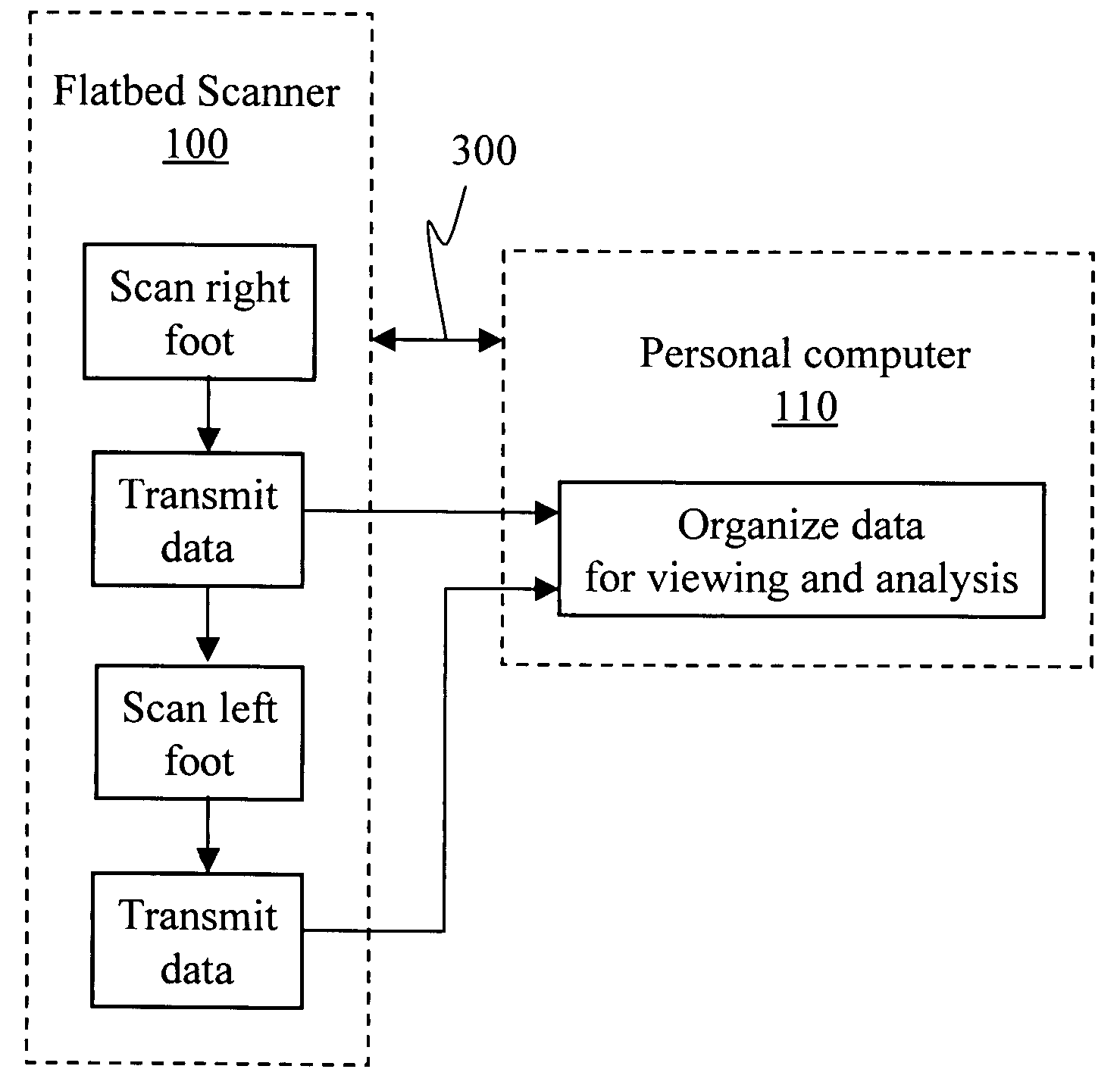
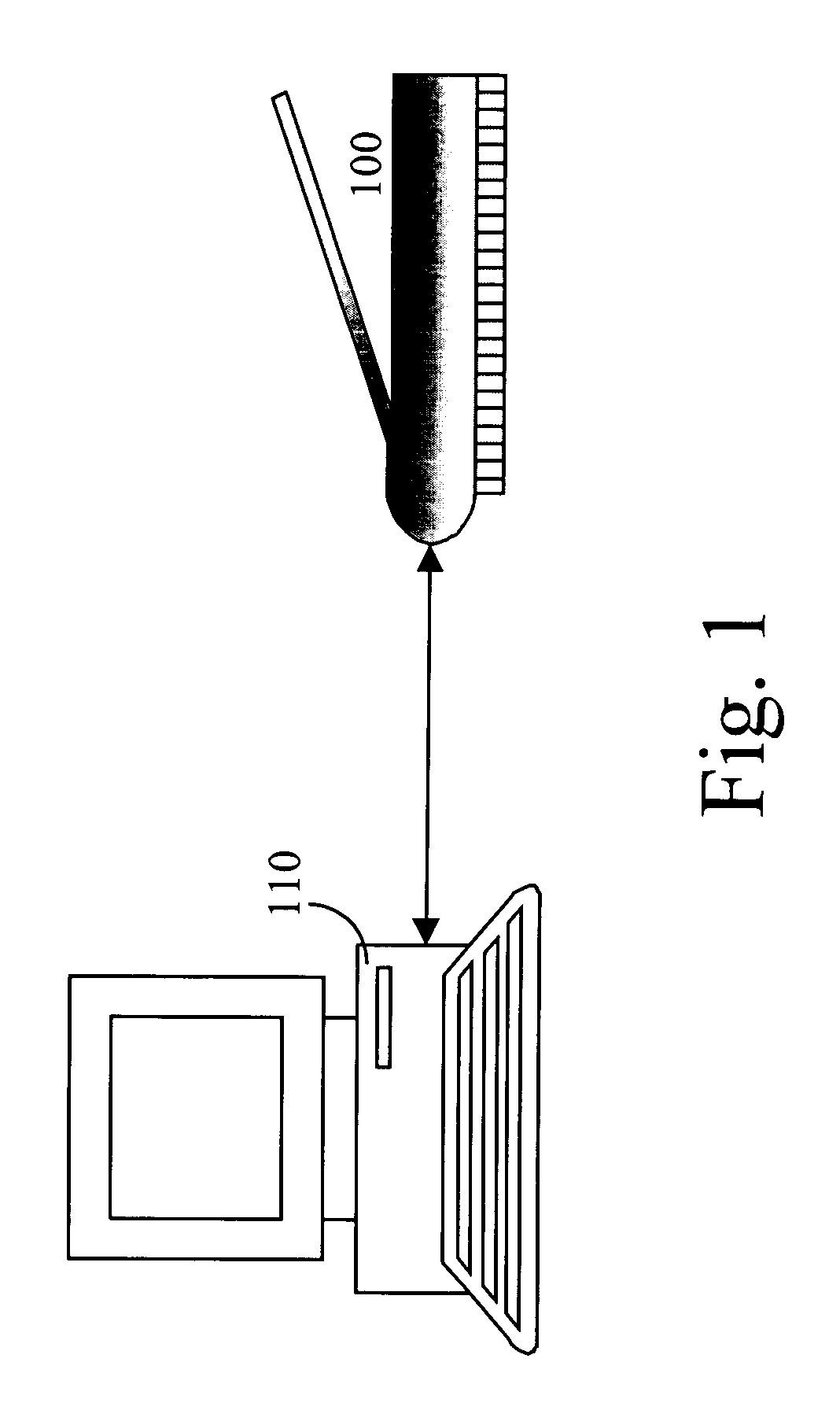
[0020] A flatbed scanner 100, depicted in FIG. 1 is used in the present invention to obtain electronic color images of a patient's feet. The scanner is connected, electronically, to a personal computer 110. Image processing software (see Appendix) within the computer 110 organizes the data to present them most conveniently to an operator.

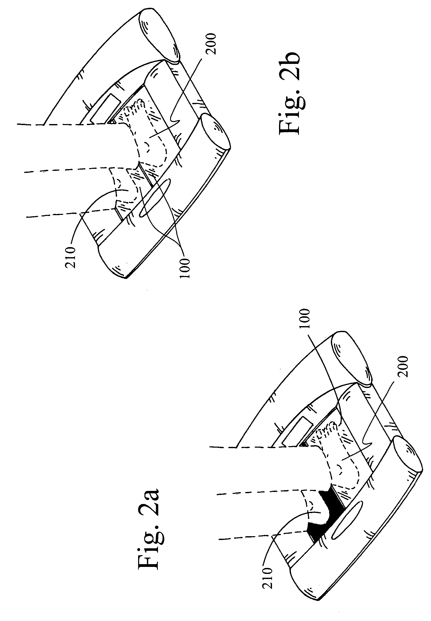
[0021] In FIG. 2, representative configurations for flatbed scanners 100 are shown with a patient standing thereon. In FIG. 2a, a single-scanner unit is shown. Only the right foot 200, in this instance, is on the scanner 100 and being scanned. The left foot 210 is on a surface that is at the same elevation as the flatbed scanner 100 so the patient may stand normally. The left foot 210 will be scanned after the patient is repositioned with the left foot 210 on the flatbed scanner 100. In FIG. 2b, both feet 200, 210 are on scanners 100. The feet 200, 210 may be scanned simultaneously or sequentially. The present invention is not limited to the physic...


PUM


Abstract

Measurements for corrective footwear, orthopedics, and orthotics have traditionally been obtained through three-dimensional casts of a foot. Digital technology opens an avenue of utilizing a digital image in place of the cast. Using a single or dual flatbed scanner and a computer, all the data required to construct a corrective device may be obtained from a scan or scans of the foot. Observed features and color variations, as well as physical measurements are used to overcome imperfections of a patient's foot.

Description

BACKGROUND OF THE INVENTION [0001] 1. Field of the Invention [0002] This invention relates generally to a method and apparatus for obtaining foot images for use in making orthopedic appliances. More particularly, the present invention is connected with the use of a flat-bed scanner for obtaining foot measurements for the making of arch supports, orthotics, custom shoes, and custom sandals. [0003] 2. Background Art [0004] In the making of orthopedic appliances such as custom orthotics, custom shoes and custom sandals, all referred to herein as “corrective orthotics,” to aid in the correction or prevention of malformations of the feet, it is necessary to first obtain an image of the foot. Measurements are then taken of the image for the purpose of duplicating the contours of the foot. For accuracy, the foot image must be taken while the foot is positioned in a normal weight bearing condition. The conventional practice, which has remained unchanged for years, is to make a depression wi...

Claims


Application Information

Patent Timeline
IPC IPC(8): A43D1/02A61B5/107A61F5/14
CPCA43D1/025A61F5/14A61B5/1074A61B5/0064
Inventor GREENAWALT, KENT S.BENNETT, DWAYNE H.
Owner FOOT LEVELERS
Why Eureka
Try Eureka