Friction clutch

a clutch and friction technology, applied in the field of friction clutches, can solve problems such as increased manufacturing costs

Inactive Publication Date: 2005-03-24
LUK LAMELLEN & KUPPLUNGSBAU BETEILIGUNGS KG
View PDF5 Cites 1 Cited by
  • Summary
  • Abstract
  • Description
  • Claims
  • Application Information

AI Technical Summary

Benefits of technology

[0006] The object is achieved with a friction clutch, especially a double clutch, having a clutch housing on which at least one lever is pivotally supported that is coupled with a pressure lever for actuation of a pressure plate. The pressure lever is formed as a single-piece, stamped element with a blind bore formed at one end and a throughbore at the other end, wherein the longitudinal axis of the throughbore is arranged substantially perpendicular to the longitudinal axis of the blind bore. In that way, subsequent machining, as it is necessary with forged parts, can be eliminated.
[0008] A preferred embodiment of the friction clutch is characterized in that the blind bore is formed so that the material surrounding the blind bore is compressed. By the compression of the material surrounding the blind bore, sufficient strength is achieved without an expensive heat treatment of the pressure lever.
[0010] A further preferred embodiment of the friction clutch is characterized in that a collar is formed on the pressure lever on one side in the region of the throughbore. By virtue of the formed collar the length of the throughbore is enlarged. In that way, improved support is achieved in the installed condition of the pressure lever.
[0014] Another object of the invention is to produce a friction clutch, especially a double clutch, with a clutch housing on which is pivotally supported at least one lever that cooperates with an eyebolt for operation of a pressure plate, that has a simple design, and that can be manufactured inexpensively.
[0015] The object is achieved with a friction clutch, especially a double clutch, with a clutch housing on which at least one lever formed as a single-piece stamped element is pivotally supported, which cooperates with an eyebolt for operation of a pressure plate. The eyebolt is arranged with a thread formed at one end and a throughbore formed at the other end, the longitudinal axis of which is arranged substantially perpendicular to the longitudinal axis of the thread. That results in the advantage that expensive machining and assembly of individual parts can be eliminated. The stamped eyebolt is preferably formed by a descending tool so that the part falls by itself out of the tool of the press that is utilized for stamping.
[0016] A preferred embodiment of the friction clutch is characterized in that a collar is formed on the eyebolt on one side in the region of the throughbore. The length of the throughbore is thus enlarged by the formed collar. In that way, improved support is attained in the installed condition of the eyebolt.

Problems solved by technology

Conventional friction clutches are often equipped with forged pressure levers that must be machined in a costly operation.
In addition, pressure levers are also utilized that are composed of several stamped elements, the assembly of which leads to increased manufacturing costs.

Method used


Image

  • Friction clutch
  • Friction clutch
  • Friction clutch

Examples


Embodiment Construction

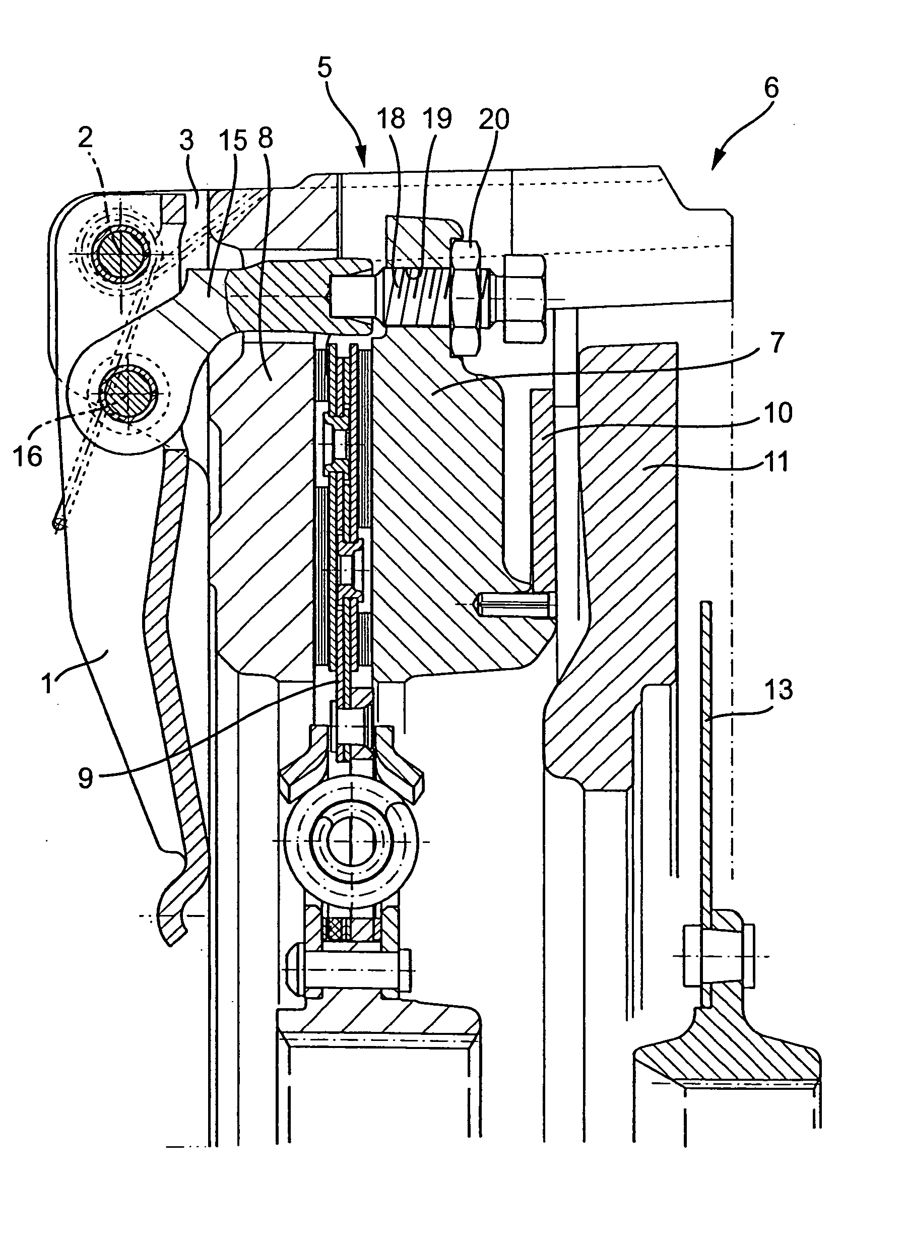
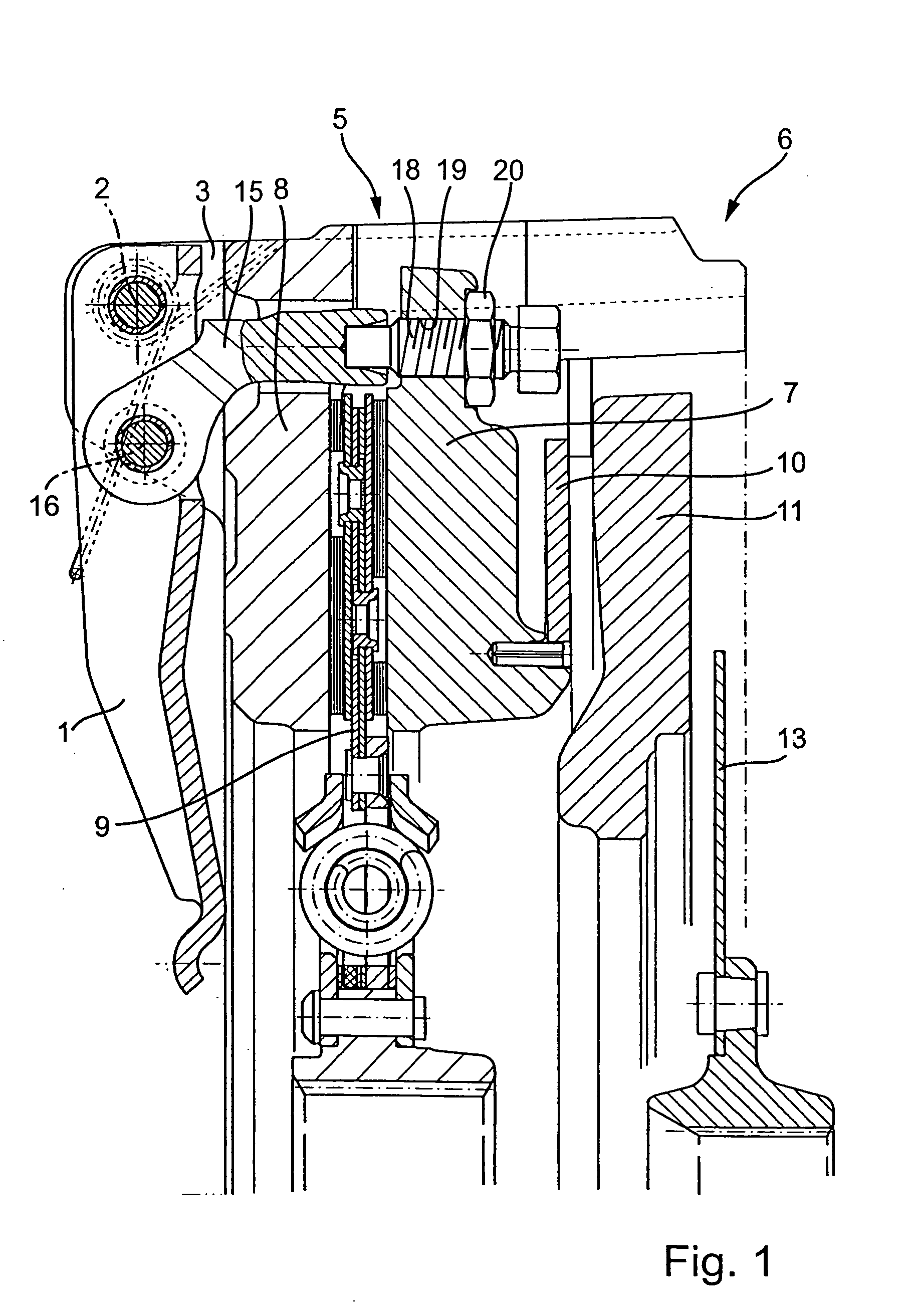
[0035] A double clutch is shown in a sectional view in FIG. 1, the actuation system of which includes an actuation lever 1 that is pivotally supported on a housing 3 with the aid of a pin 2. The double clutch includes a first clutch 5 and a second clutch 6. The first clutch 5 includes a pressure plate 7 and a counterpressure plate 8, between which a first clutch disk 9 with friction linings can be clamped. The pressure plate 7 is acted upon by a disk spring 10, the other side of which rests against a pressure plate 11 of the second clutch 6. A second clutch disk 13 can be clamped between the pressure plate 11 and an associated counterpressure plate (not shown).

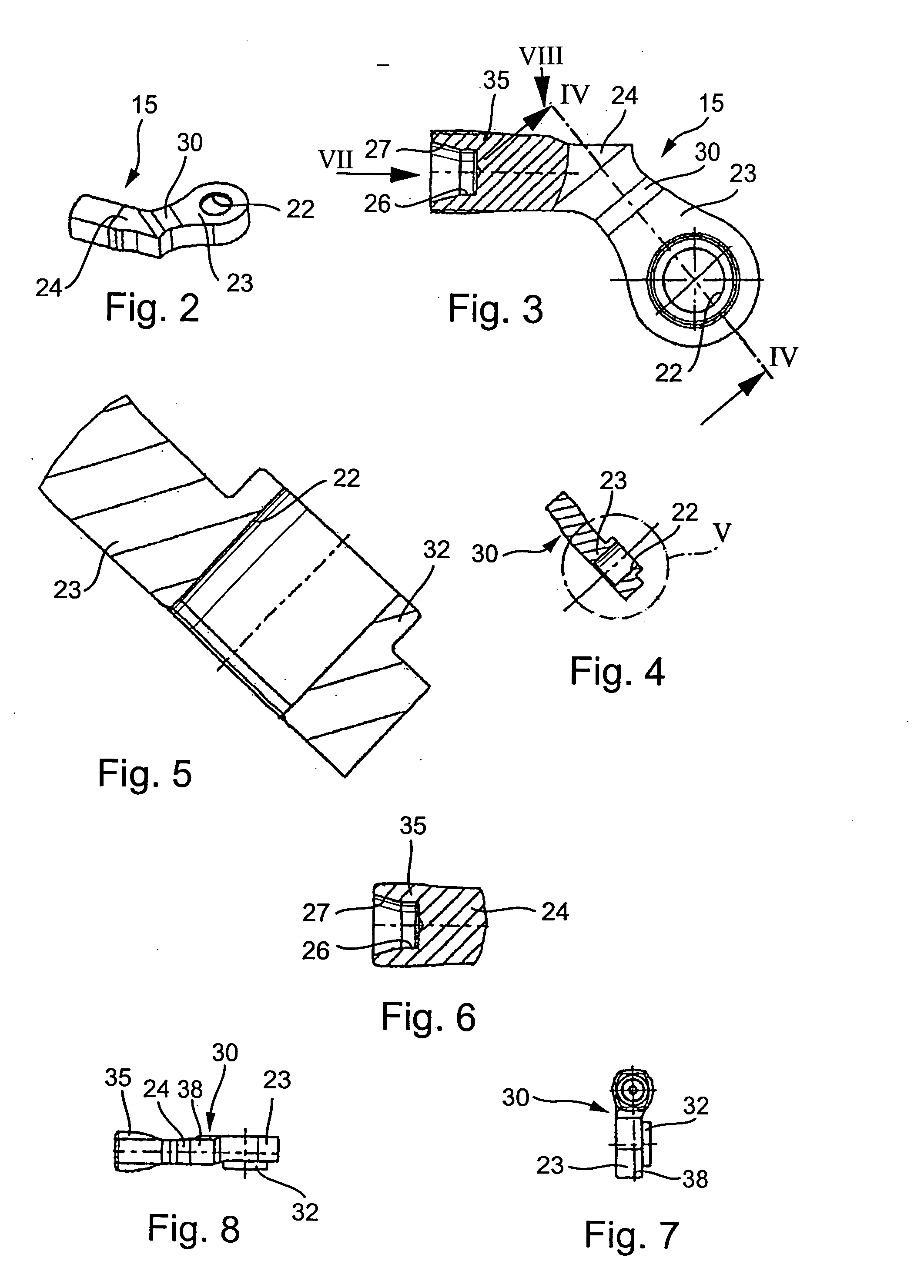
[0036] A pressure lever 15 is pivotally supported on the actuation lever 1 with the aid of a pin 16. The free end of the pressure lever 15 interacts cooperatively with a stop screw 18 that is screwed into a tapped hole 19 that is provided radially outwardly in the pressure plate 7. The stop screw 18 is set in position in tapp...


PUM


Abstract

A friction clutch, especially a double clutch, with a clutch housing on which at least one actuation lever is pivotally supported. A connecting member in the form of a pressure lever or an eyebolt is coupled with the actuation lever for actuation of a clutch pressure plate. The pressure lever or the eyebolt is formed as a one-piece stamped element to minimize machining and assembly costs.

Description

BACKGROUND OF THE INVENTION [0001] 1. Field of the Invention [0002] The invention relates to a friction clutch, especially a double clutch, with a clutch housing on which is pivotally supported at least one lever that is coupled with a pressure lever for operation of a pressure plate. [0003] 2. Description of the Related Art [0004] Conventional friction clutches are often equipped with forged pressure levers that must be machined in a costly operation. In addition, pressure levers are also utilized that are composed of several stamped elements, the assembly of which leads to increased manufacturing costs. [0005] An object of the invention is therefore to produce a friction clutch, especially a double clutch, with a clutch housing on which at least one lever is pivotally supported and is coupled with a pressure lever to operate a pressure plate, wherein the pressure lever can be simply formed and economically manufactured. SUMMARY OF THE INVENTION [0006] The object is achieved with a...

Claims


Application Information

Patent Timeline
Patent Type & Authority Applications(United States)
IPC IPC(8): F16D13/58F16D13/70F16D23/12
CPCF16D13/58F16D13/70Y02T10/76F16D2013/706F16D23/12F16D2023/126
Inventor GANDER, GERHARDWEYDMANN, PATRICK
Owner LUK LAMELLEN & KUPPLUNGSBAU BETEILIGUNGS KG
Why Eureka
Try Eureka