
Drive system for reducing the polygon effect in continuous drive chains of escalators or moving walkways

a technology of driving system and escalator, which is applied in the direction of escalators, building lifts, conveyors, etc., can solve the problems of high construction effort in front of in the area of the reversing wheel, adversely affecting the quiet running of the escalator or the moving walkway, and achieve the effect of reducing the polygon

Inactive Publication Date: 2005-03-24
KONE CORP
View PDF3 Cites 5 Cited by
  • Summary
  • Abstract
  • Description
  • Claims
  • Application Information

AI Technical Summary

Benefits of technology

[0011] It is an object of the invention to provide a new drive system for escalators and moving walkways, which are in particular equipped with plate link chains having a greater pitch, in which the direction of movement of both drive chains having a normal pitch and drive chains having a greater pitch can be changed in the area of reversing elements with a minimized polygon effect. This can be realized both in the entry and the exit area of the respective drive chain.
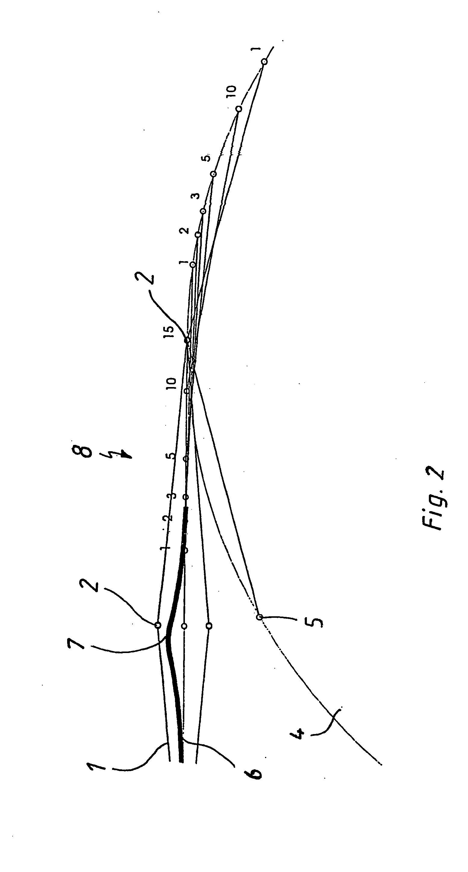
[0013] In comparison to the state of the art, the object of the invention enables efficient elimination of speed differences between the drive chain and the reversing element in the entry area, on the one -hand, and optionally also in the exit area, on the other hand. This results from the fact that, in single or several chain links, respectively at least one roller or chain roll of the drive chain is or are moved out of their direction of movement before entering or after leaving the reversing element, which is preferably configured as a chain wheel. The entry / exit area cannot be considered as a point, but it covers a defined area in front of or behind the respective reversing element that is dependent on the chain pitch.
[0015] The invention takes advantage of the fact that it is possible to influence the position of the upstream chain links / chain rolls or rollers as a function of the phase position of the chain wheel. In such positions, in which a higher speed is geometrically caused by the chain engagement, the position of one or several of the mentioned chain links, respectively the rollers or chain rolls, shall be influenced by the curved shape of the upstream or downstream path, such that a speed reduction / increase is realised, which, in sum, reduces the speed variations in the entry / exit area of the drive chain. Simultaneously an equalization of the polygon effect is obtained, since the speed -adaptations are no more felt as impacts by the users of the escalator or the moving walkway. The quiet running and the life time of the components of the escalator or moving walkway can be considerably increased. The polygon effects, which are caused by the greater chain pitches of the step or pallet chain, and which have a negative effect on the reversing element that is configured as a chain wheel and optionally on the handrail wheel, are almost eliminated by the subject of invention. The economically positive effects of a greater chain pitch (reduction of the chain price) can thus be efficiently integrated into existing drive systems with the use of the invention.
[0018] The subject of invention can be principally used for all types of escalators or moving walkways, but preferably for the drive chains of an escalator or a moving walkway, which can be used in the interior of buildings. Thus, it is not only the effect of the greater chain pitch, but the combination of the same with suitable measures for reducing the polygon effect, which leads to an economically interesting solution, in particular for drives of department store escalators and moving walkways.

Problems solved by technology

However, it is possible that these desired greater chain pitches will cause problems with respect to the polygon effect during the reversing and possibly with respect to the synchronous drive of the handrail.
However, during the reversing of the reversing chains, in particular with greater chain pitch, the existing polygon effect causes problems.
This measure permits an efficient reduction of the polygon effect, but the construction effort both in front of and in the area of the reversing wheel is high.
In the reversing of the chains of escalators or moving walkways by means of a chain wheel, polygon and revolution effects occur, which in particular adversely affect the quiet running of the escalator or the moving walkway.
When engaging the chain wheel, the chain rolls and the teeth of -the chain wheel have different velocities, which cause impacts.

Method used


Image

  • Drive system for reducing the polygon effect in continuous drive chains of escalators or moving walkways
  • Drive system for reducing the polygon effect in continuous drive chains of escalators or moving walkways
  • Drive system for reducing the polygon effect in continuous drive chains of escalators or moving walkways

Examples


Embodiment Construction

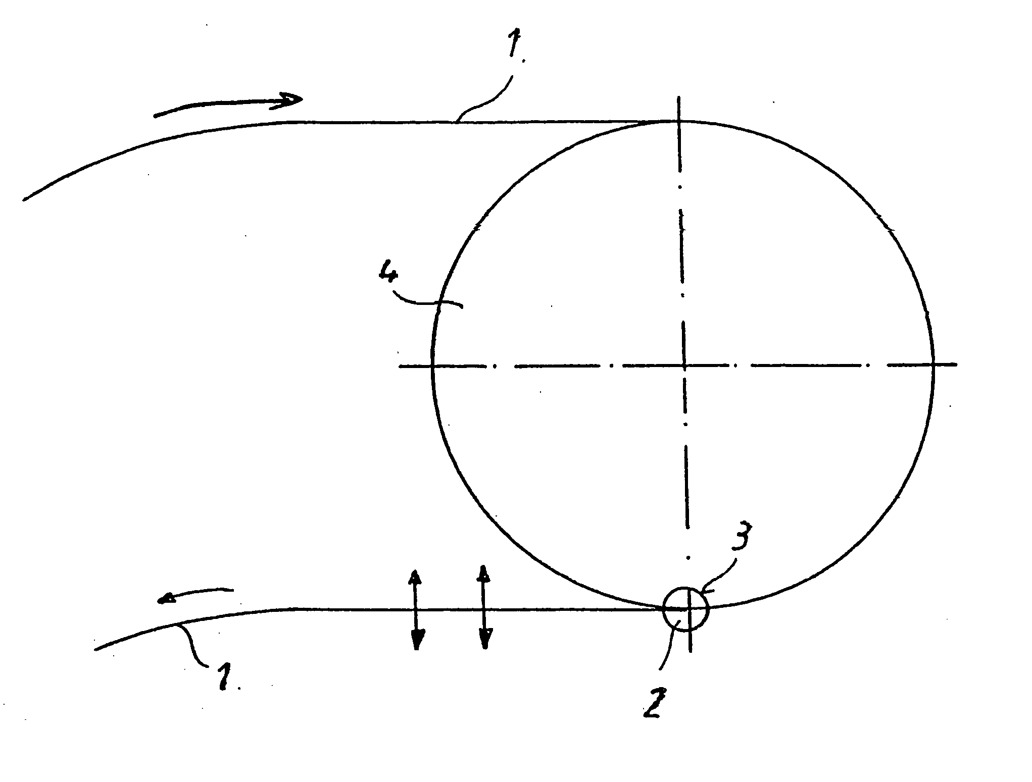
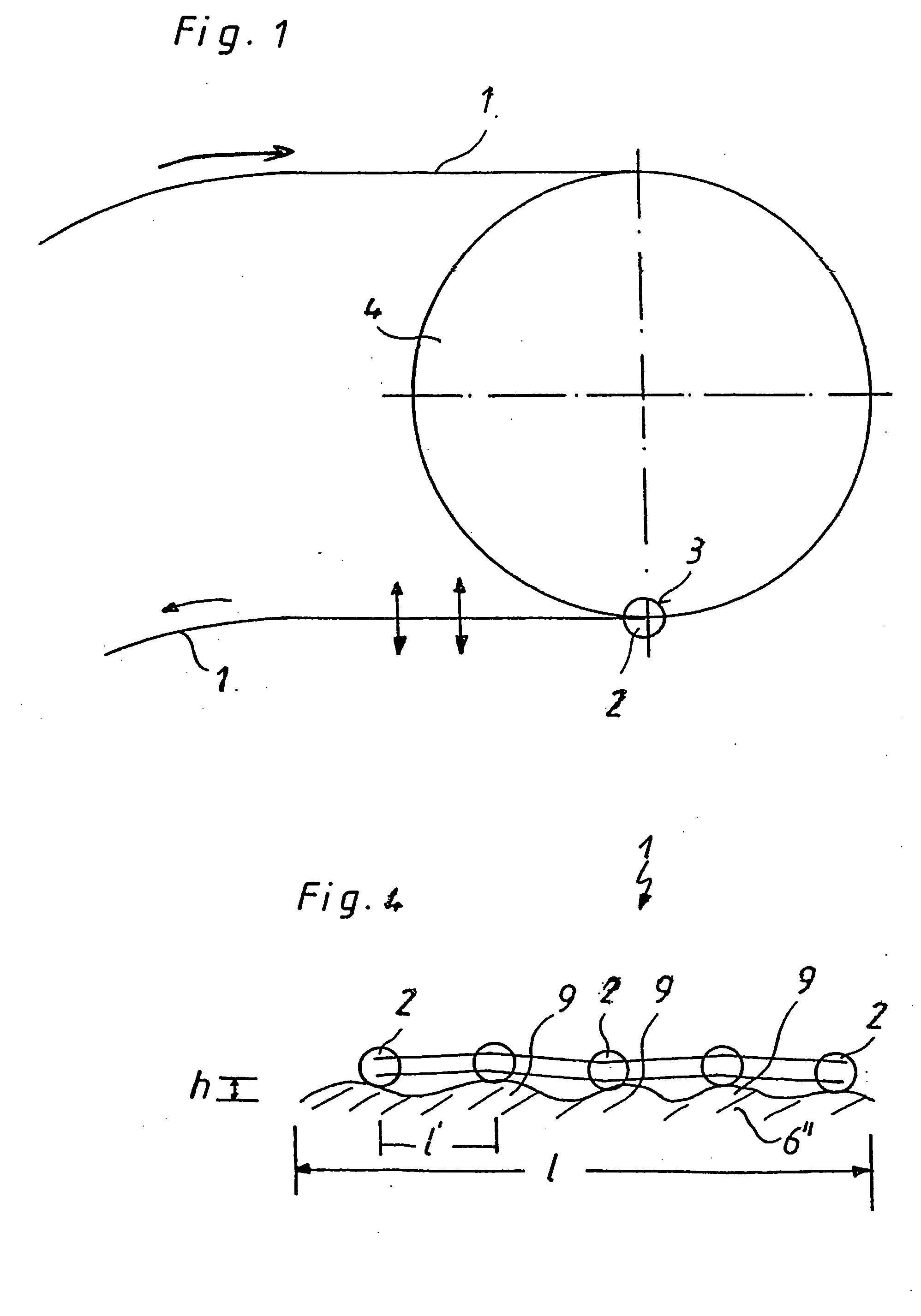
[0024] Referring to FIG. 1, there is shown a reversing area of a drive chain 1 for an escalator (not shown). Drive chain 1 is configured as a plate link chain, having a plurality of chain rolls 2. The direction of movement of chain 1, indicated by the arrows, is changed by a reversing element which is configured as a chain wheel 4 having recesses 3 for receiving the chain rolls. Upon engaging the chain wheel 4, the chain rolls 2 and the teeth of the chain wheel 4 have different speeds, which lead to impacts. The revolution effect is caused by the angular momentum which is transmitted from the chain wheel 4 onto the chain links and thus onto the steps (not represented) of the escalator. After the drive chain 1 has run out of the chain wheel 4, this angular momentum is temporarily maintained due to the inertia of the system, which leads to the so called curling of the drive chain 1

[0025] The curling is symbolically represented by the upward and downward arrows shown in FIG. 1. The afo...


PUM


Abstract

A drive system for an escalator or a moving walkway includes at least one drive motor, at least one drive chain and a reversing element for the drive chain. A device for modifying the speed of the drive chain is arranged in at least an entry or exit area of the reversing element.

Description

CROSS-REFERENCE TO RELATED APPLICATION [0001] This is a continuation of International Patent Application No. PCT / EP03 / 04145 filed Apr. 22, 2003, designating the U.S. and claiming priority of German Patent Application Nos. 102 18 374.0 filed Apr. 25, 2002, and 102 22 992.9 filed May 24, 2002, the disclosures of all of the foregoing applications being incorporated herein by reference. [0002] The subject matter of this application is additionally related to the subject matter of the following U.S. Patent Applications: (1) concurrently filed and co-owned application No. ______ (Attorney Docket No. 317934-206852) filed in the name of Alexander Pietz, titled “Drive System For Exsalators or Moving Walkways;” (2) No. 10 / 728,852 filed Dec. 8, 2003; (3) No. 10 / 693,825 filed Oct. 27, 2003; and (4) No. 10 / 464,555 filed Jun. 19, 2003. BACKGROUND OF THE INVENTION [0003] The invention relates to a drive system for escalators and moving walkways. [0004] It is generally known that escalators or movi...

Claims


Application Information

Patent Timeline
Patent Type & Authority Applications(United States)
IPC IPC(8): B66B23/02
CPCB66B23/022
Inventor PIETZ, ALEXANDER
Owner KONE CORP
Learn More