Plasma display panel

a technology of display panel and plasma, which is applied in the manufacture of electrode systems, instruments, electric discharge tubes/lamps, etc., can solve the problems of growing problems such as mis-discharge or accidental discharge, and achieve the effects of reducing mis-discharge, improving electrode design, and reducing the amount of xe gas

Inactive Publication Date: 2005-03-24
SAMSUNG SDI CO LTD
View PDF27 Cites 13 Cited by
  • Summary
  • Abstract
  • Description
  • Claims
  • Application Information

AI Technical Summary

Benefits of technology

[0008] It is also an object of the present invention to provide an improved design for a PDP that reduces mis discharging between discharge cells when the PDP is a high definition display with elevated levels of Xe gas in the discharge cells.
[0009] It is also an object of the present invention to provide improved electrode design in a PDP to prevent

Problems solved by technology

However, as PDP's become more high definition and thus the structures within the display become

Method used


Image

  • Plasma display panel
  • Plasma display panel
  • Plasma display panel

Examples


Embodiment Construction

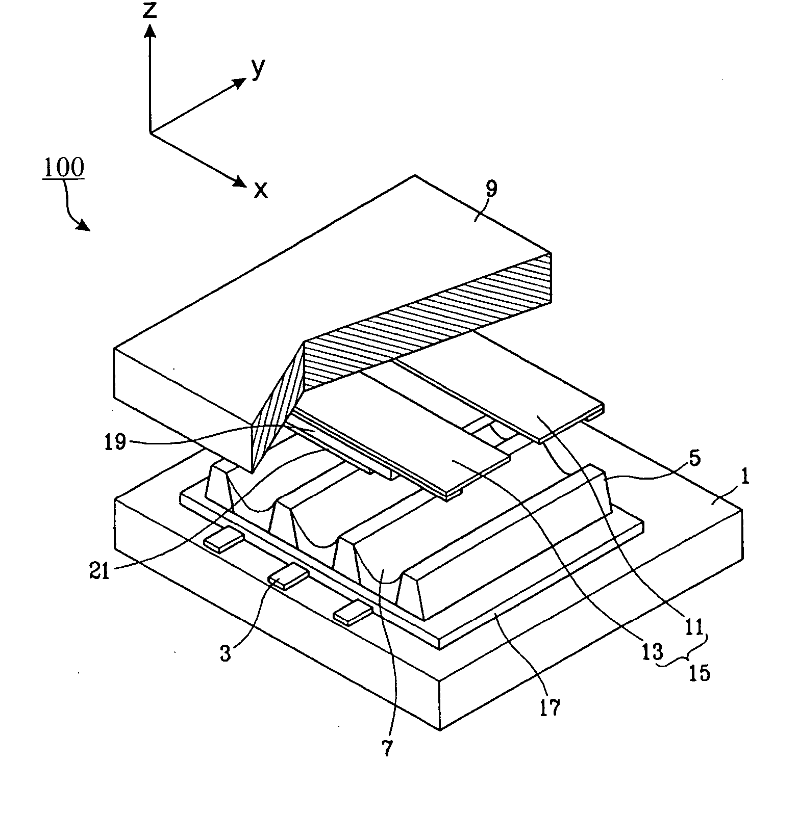
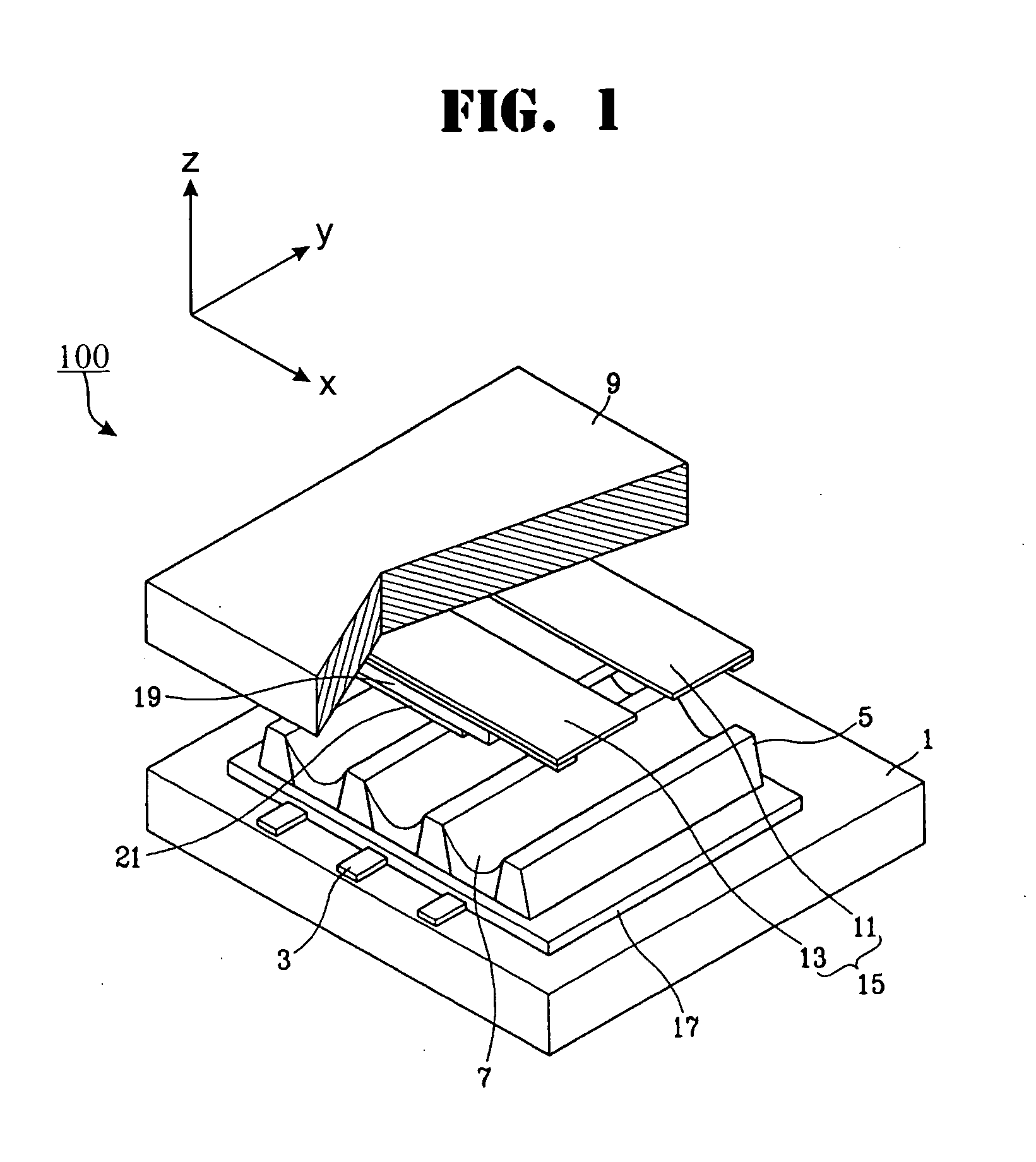
[0023] Turning now to the figures, FIG. 1 illustrates an alternating current type PDP 100. PDP 100 of FIG. 1 includes an address electrode 3, a barrier rib 5, and a phosphor layer 7 formed on a rear substrate 1 at respective discharge cells. On the front substrate 9 is formed a discharge sustain electrode 15 which is a scanning electrode 11 paired with a display electrode 13. Dielectric layers 17 and 19 cover the address electrode 3 and the discharge sustain electrode 15, respectively. The discharge cell is internally filled with a discharge gas (mainly a mixture gas of Ne—Xe). In PDP 100 of FIG. 1, an MgO protective layer 21 is formed to cover dielectric layer 19.

[0024] In the PDP 100 of FIG. 1, when an address voltage Va is applied between the address electrode 3 and the scanning electrode 11, address discharging occurs within the discharge cell so that wall charges build up on the dielectric layer 19 near the scanning and the display electrodes 11 and 13 as well as on the dielec...


PUM


Abstract

A plasma display panel includes designed to improve optical efficiently and to reduce misdischarging between discharge cells. The address electrodes have varying widths so that they are narrow in discharge cells and are relatively wide outside of discharge cells. Discharge gas filling the discharge cells have an elevated Xe content, preferably 10 to 30%. Other variations further include having striped and matrix patterned barrier ribs, forming the discharge sustain electrodes in tabs extending in pairs into the middle of the discharge cells, and varying the width of address electrodes at various locations outside of the discharge cells.

Description

CLAIM OF PRIORITY [0001] This application makes reference to and claims all benefits accruing under 35 U.S.C. §119 from an application for PLASMA DISPLAY PANEL earlier filed in the Korean Intellectual Property Office on the 4th day of September 2003 and there duly assigned Serial No. 2003-61862. BACKGROUND OF THE INVENTION [0002] 1. Field of the Invention [0003] The present invention relates to a plasma display panel, and in particular, to a plasma display panel with an improved structure for address electrode that prevents mis-discharging in discharge cells, especially in plasma display panels with high definition. [0004] 2. Description of Related Art [0005] Generally, a plasma display panel (referred to hereinafter simply as a “PDP”) is a display device which displays images by exciting phosphors with vacuum ultraviolet rays generated due to discharging of gas within a discharge cell. PDPs are classified into an alternating current type and a direct current type, depending upon th...

Claims


Application Information

Patent Timeline
IPC IPC(8): H01J9/00H01J11/12H01J11/22H01J11/24H01J11/26H01J11/34H01J11/36H01J11/50
CPCH01J11/12H01J2211/265H01J11/26H01J11/50
Inventor KANG, TAE-KYOUNGKIM, YONG-JUN
Owner SAMSUNG SDI CO LTD
Why Eureka
Try Eureka