Imaging apparatus

a technology of imaging apparatus and lens, which is applied in the field of imaging apparatus, can solve the problems of difficult to compose a camera small, difficult to make the thickness of the camera thinner than a certain thickness, and large sum of the thickness of the lens, so as to improve the usability and improve the zoom magnification.

Inactive Publication Date: 2005-03-24
KYOCERA CORP
View PDF6 Cites 25 Cited by
  • Summary
  • Abstract
  • Description
  • Claims
  • Application Information

AI Technical Summary

Benefits of technology

[0032] As one of the embodiments of the invention, a support pillar is provided to one of the upper or lower cover or to both of the covers composing the housing of the operation unit to pass through the holes provided near the center of the main board to hold the main board in place loosely to accommodate to a case distortion occurs in the housing, so that even in case the apparatus is dropped through carelessness for example and the housing is temporarily deformed, the main board is not deformed. Therefore, such a trouble that the CPU, etc. mounted on the main board is removed off from the board can be prevented.
[0054] By calculating by said control means the focal distance of the zoom lens using the distance from the camera to the subject to be shot calculated based on the signal from the focusing means of the zoom lens and the predetermined magnification and allowing the control means to stop changing zoom magnification at the calculated focal distance, shooting can be done by keeping the image on the display always to a certain size either when shooting a self-portrait with the camera held by the hand of the user or fixed to a tripod. Therefore, an imaging apparatus of very good usability can be provided.

Problems solved by technology

However, when an electronic camera is constructed such that the lens unit is protruded from the camera body as is the case with a conventional camera using a rolled film, it is difficult to make the thickness of the camera thinner than a certain thickness because of the zooming mechanism and thickness of the lens unit even in the case of a lens unit sinking type camera.
Further, the zoom lens consists of a plurality of lens groups as mentioned above, so the number of lenses increases with increased magnification, the sum of the thickness of lenses becomes fairly large, and it is difficult to compose a camera small in thickness
Also, there is a problem that when the cam ring is provided on the outer circumference of the lens-barrel, the diameter of the lens unit becomes large resulting in an increased size of camera, which is an impeding factor for designing a low-profile camera.
However, in the camera composed to move the lens group located near the intermediate position to the range outside the optical axis range, the structure is complicated for securing accuracies of optical groups as the lens groups must be moved off to the range outside the optical axis range, and the number of component parts increases for moving off the lens groups to the range outside the optical axis range, resulting in an increase in manufacturing cost.
Further, with a camera in which intermediate lens groups or lens-barrel is immersed in the camera body by switching off the main electric source, it takes a certain time until shooting pictures becomes possible because it takes a certain time until the lens groups are protruded after the main electric source is switched on, and photo opportunity may be missed.
With this composition, the number of component parts is reduced and downsizing of camera can be achieved, on the other hand, reflectors or prisms are necessary and the structure becomes complicated, which results in an increase in weight and cost, so downsizing or low-profiling compared to the case of a camera provided with a cam mechanism is not conspicuous.
However, with a camera such as disclosed in Japanese Laid-Open 
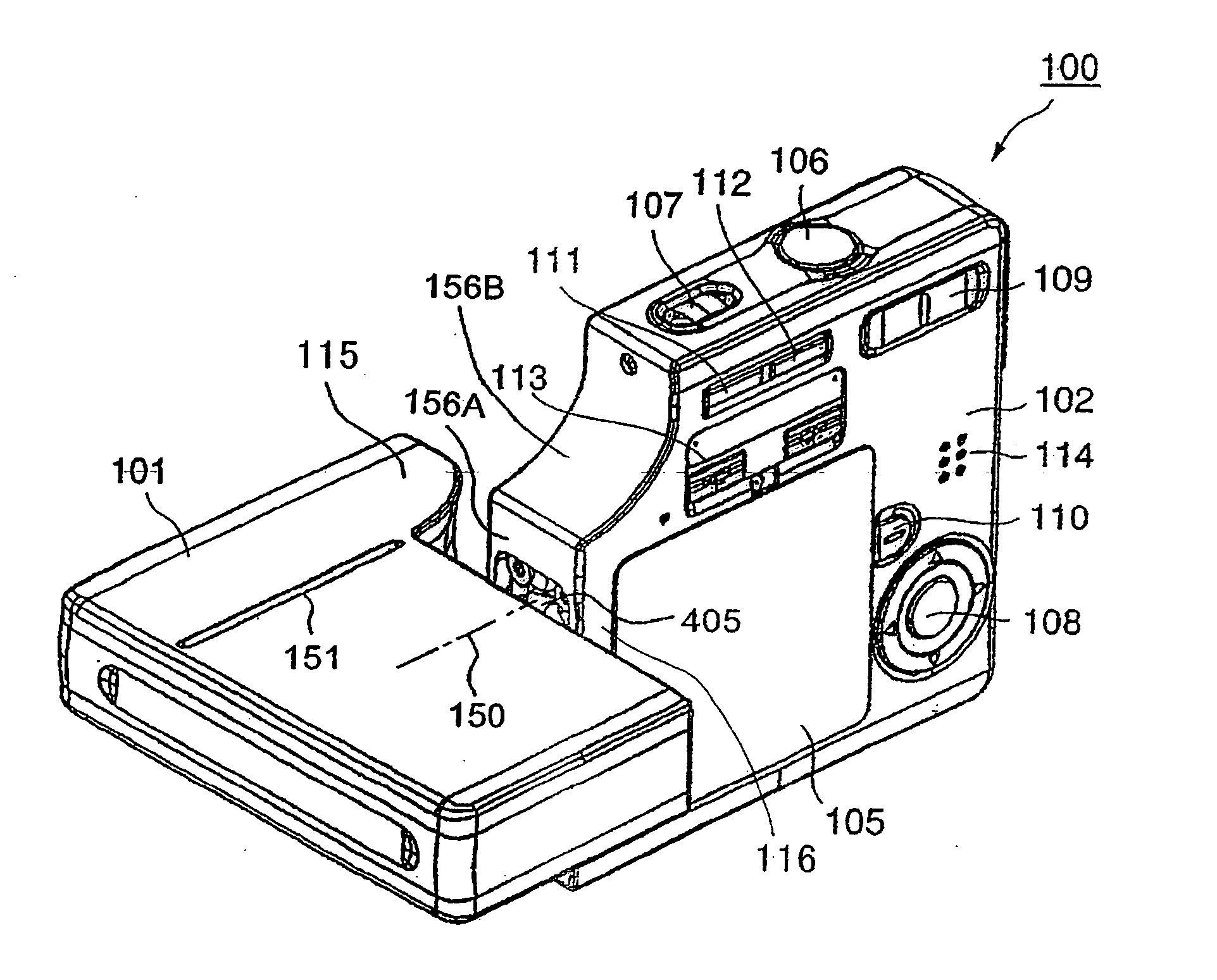
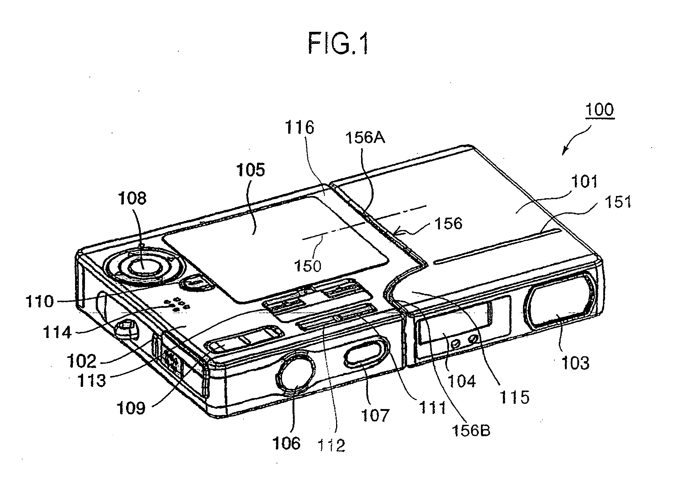
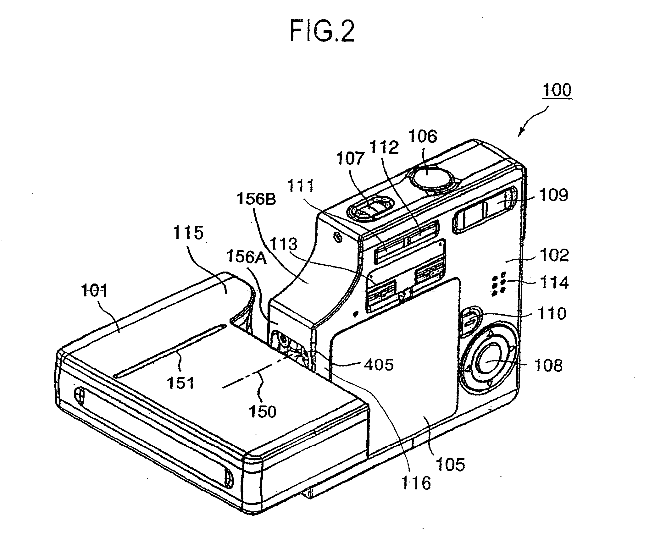
Patent Application No. 4-158682 or No. 7-23259, there is a problem in addition to the problem mentioned above that, although it is possible to see the display when the window for taking pictures is directed to a subject to be shot at the level of user's eyes, it is difficult to check the coverage of picture on the display when shooting the user him-or-herself or a subject near the ground or over the heads of a crowd because the display is disposed on the opposite side of the window for taking pictures, and the user has no choice but to shoot by the seat of his pants.
The camera disclosed in Japanese Laid-Open Patent Application No. 7-23259 is composed such that the surface of the display is parallel to the light axis, so when shooting with the camera held at the level of user's eyes, the user can check the coverage of picture on the display, but it is difficult to check the coverage of picture on the display when shooting with the camera held at the position lower than the level of user's eyes.
Due to the operation buttons and grip portions, it is difficult to get the camera in and out of the breast pocket of one's shirt or back pocket of one's pants smoothly.
Therefore, the operation buttons and command dials can not be operated by a user's thumb but need to be operated by his forefinger or other fingers, and further to operate those buttons while viewing the display is not possible.
Further, with the electronic camera composed such that the imaging unit integrating the lens and image pickup device is rotatable relative to the camera body provided with the display as disclosed in said Japanese Patent No. 2931907, it is possible to shoot the user him-or-herself by rotating the imaging unit toward the user (hereafter, this shooting is referred to as self-portrait shooting), however, when practicing self-portrait shooting, the user him-or-herself carries the camera and object distance is limited within 1 m. Therefore, the image of the user him-or-herself is displayed on the display as a large image and magnification should be adjusted each time of self-portrait shooting.
However, with a camera of which the lens is drawn back when not shooting, a certain time is necessary before shooting is ready after the electric source is switched on, that is, start-up time is long, and it may happen to lose photo opportunity.
However, when deterioration in precision in the zoom lens is caused by vibration, the zoom lens is not reset and there may happen that the image of photograph is deteriorated.

Method used


Image

  • Imaging apparatus
  • Imaging apparatus
  • Imaging apparatus

Examples


Embodiment Construction

[0077] A preferred embodiment of the present invention will now be detailed with reference to the accompanying drawings. It is intended, however, that unless particularly specified, dimensions, materials, relative positions and so forth of the constituent parts in the embodiments shall be interpreted as illustrative only not as limitative of the scope of the present invention.

[0078] In the drawings, the each of the same constituent parts is marked with identical numeral. FIG. 1 is an external view of an embodiment of the electronic camera according to the present invention, FIG. 2 is a view when the lens of the electronic camera according to the present invention is directed toward a subject to be shot, FIG. 3 is a view when the lens of the electronic camera according to the present invention is directed toward the operator of the camera, and FIG. 4 is a representation showing the state of holding the camera when shooting is practiced with the lens of the electronic camera accordin...


PUM


Abstract

An imaging apparatus which is thin in thickness and has enough strength to be able to be accommodated in the breast pocket of one's shirt or back pocket of one's pants or in a handbag without bothered by a feeling of strangeness is provided. The imaging apparatus is composed of an imaging unit and an operation unit, both units being connected rotatably relative to each other by a hinge mechanism and formed into a low-profile, rectangular shape in the normal state in which the units are positioned parallel to each other. The operation unit is composed of an upper and a lower cover, a main board having a memory slot and an accommodation part for a flat type battery respectively on both flat faces thereof is contained inside the covers, the main board being supported by a main board supporting part or parts provided at a corner or corners inside the covers, a display is located on the memory slot side, and a control board of the imaging unit is located sideward adjacent to the battery accommodation part of the main board.

Description

BACKGROUND OF THE INVENTION [0001] 1. Field of the Invention [0002] The present invention is related to an imaging apparatus such as electronic camera capable of storing images picked up by an image pickup device in an integrated memory or in an outside memory, particularly to an imaging apparatus such as an electronic camera in which an operation unit provided with a display is hinged to an imaging unit to which a high magnification optical zooming system is mounted so that the operation unit is rotatable relative to the imaging unit and which is constructed as a small-sized, low-profile, light weight, and user-friendly camera. [0003] 2. Description of the Related Art [0004] With an electronic camera provided with an image pickup device such as a CCD and capable of memorizing images as digital data, pictures photographed can be seen immediately without developing, printing, etc. An image pickup devices such as a CCD is becoming smaller-sized than a film roll year by year in spite o...

Claims


Application Information

Patent Timeline
Patent Type & Authority Applications(United States)
IPC IPC(8): G03B17/02G03B19/02H04N5/225H04N5/232
CPCH04N5/2252H04N23/51H04N5/765H04N23/60
Inventor OKUTANI, TSUYOSHIYOKOTA, TADASHI
Owner KYOCERA CORP
Why Eureka
Try Eureka