Calibration arrangement for a scanner

Inactive Publication Date: 2005-03-24
EASTMAN KODAK CO
View PDF8 Cites 9 Cited by
  • Summary
  • Abstract
  • Description
  • Claims
  • Application Information

AI Technical Summary

Benefits of technology

The low spatial frequency signature of this scattering induced non-uniformity facilitates solutions to the drawbacks and problems discussed above. Non-uniformity compensation need only be determined at a few locat

Problems solved by technology

This subsequent calibration step results in an additiona

Method used


Image

  • Calibration arrangement for a scanner
  • Calibration arrangement for a scanner
  • Calibration arrangement for a scanner

Examples


Embodiment Construction

In a feature of the present invention, the low spatial frequency signature of scattering induced non-uniformity allows for various solutions to the drawbacks and problems discussed above. For example, any non-uniformity compensation need only be determined at a few points or pixel locations, by sparsely sampling the image as this is sufficient to reconstruct a low spatial frequency signature. In the context of the present invention, low spatial frequency corresponds to frequencies on the order of 5 cycles or less per full field. In addition, since only low frequency information is needed, compensation techniques that are subject to high frequency noise can be considered as high frequencies can be filtered to eliminate this noise without modifying the low frequency compensation. There are several solutions that utilize either or both of these techniques.

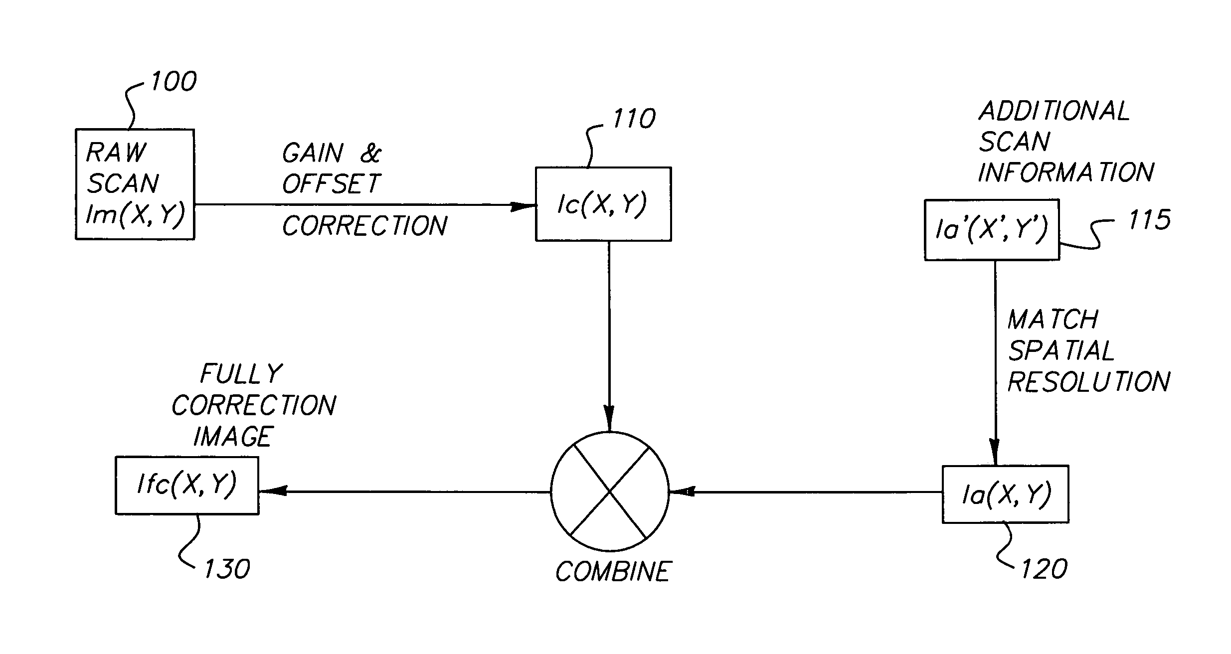
FIG. 3 schematically illustrates a system or flow chart in accordance with the present invention which details steps that can be u...


PUM


Abstract

The present invention relates to a low spatial frequency calibration arrangement for scanning systems. In the method and system of the present invention, calibration is performed to compensate for non-uniformities introduced when light scattering media is scanned. This calibration results in a non-uniformity mapping at each scanning pixel location.

Description

FIELD OF THE INVENTION The present invention relates generally to an apparatus for scanning digital color image information from media such as photographic film and more particularly, to a method for calibrating a scanning system. BACKGROUND OF THE INVENTION Scanners are typically calibrated by scanning “open gate” or without any media in the scanning aperture. This calibration technique is useful in removing gain and offset non-uniformities that result from the scanning lens / optics, scanning sensor non-uniformities, and illumination intensity non-uniformities (see, for example, U.S. Pat. No. 5,563,723). However, when scanning media wherein there exists substantial scattering, such as films with significant quantities of retained silver, this calibration method may not remove important non-uniformities. These non-uniformities result from forward scattering caused by the media that alters the angular distribution of illumination, and backward scattering caused by the media that cou...

Claims


Application Information

Patent Timeline
IPC IPC(8): H04N1/401H04N1/60
CPCH04N1/6094H04N1/401
Inventor WELDY, JOHN A.KULPINSKI, ROBERT W.
Owner EASTMAN KODAK CO
Why Eureka
Try Eureka