Dual propeller drive for ski boat

a technology for ski boats and propellers, which is applied in the direction of propulsive transmission, marine propulsion, and can solve the problems of increasing the cost of ski boats, requiring greater power, and heavy boats such as 28-foot boats, and achieves the effects of not reducing the maximum speed reducing the weight of the ski boat, and increasing the pulling power

Inactive Publication Date: 2005-03-24
WOLTERS KAREL L +1
View PDF8 Cites 2 Cited by
  • Summary
  • Abstract
  • Description
  • Claims
  • Application Information

AI Technical Summary

Benefits of technology

[0040] Another important advantage of the present invention is that the drive mechanism provides increased pulling power with little decrease in speed under load. Thus where one or a large number of skiers are pulled, the maximum speed of the boat is not reduced nearly as much as when a single prop engine is used. This increased pulling power also makes it easier to maintain a constant speed through a slalom course, even though this load varies substantially.
[0041] Likewise, when a skier is pulled from a sitting position on a dock, the tow boat does not lose momentum due to prop slip when the rope gets tight. A strong steady increase in speed is achieved, and this minimizes falls.
[0042] Another outstanding advantage of the two propeller drive is when a bare footed skier steps off his ski at 40 mph, the boat speed is not dramatically reduced like it is with a single prop.
[0043] The present invention also is advantageous for wake boarding. A wake board is different from a water skiing operation, because a larger wake is desired. In order to achieve a larger wake with a conventional ski boat is customary to add ballast to the boat, which causes the boat to ride lower in the water and thus increases the wake. More power is necessary to drive a boat wh

Problems solved by technology

Larger boats, such as 28-foot boats, are heavy and require greater power than smaller boats.
This increases dramatically the cost of the ski boat.
This in turn was thought to produce unacceptably reduced top sp

Method used


Image

  • Dual propeller drive for ski boat
  • Dual propeller drive for ski boat
  • Dual propeller drive for ski boat

Examples


Embodiment Construction

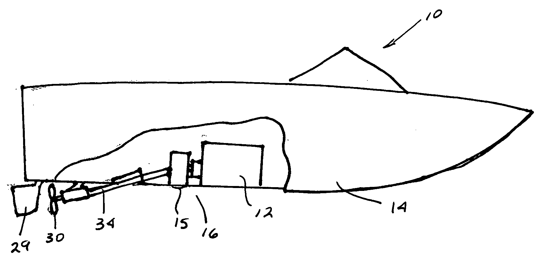
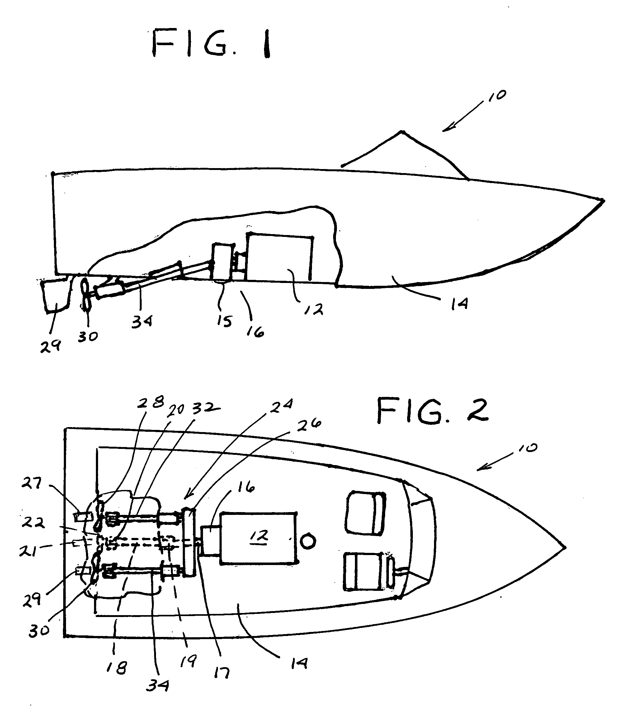
[0021] A motor boat or powerboat 10, shown schematically, includes an inboard engine 12, such as a 350 horsepower automobile engine or larger, mounted in a conventional manner inside the hull 14 of the boat. The engine has a conventional transmission 16, which typically permits the engine to be shifted between neutral, forward, and reverse gears. In the exemplary embodiment the engine transmission includes a gear reduction ratio of 1½ to 1, which means that when the engine is rotating at 3,000 rpm, the engine output shaft is rotating at 2,000 rpms.

[0022] A conventional inboard engine (which for convenience will be deemed to include the conventional engine transmission) drives the boat by means of a propeller shaft 18, which extends downwardly and rearwardly from driving engagement with an output shaft 17 of the engine through the bottom of the boat to an outer end, on which a propeller is mounted. The propeller shaft is journalled in seal 19 in the floor of the boat and in a suppor...


PUM


Abstract

A dual prop drive for a ski boat has a gear box having an input gear that is connected to an engine output shaft. The gear box has two laterally spaced output gears on opposite sides of the input gear, with the output gears being drivingly connected to the input gear. The dual prop dive unit has two propeller shafts, each of which is drivingly connected to one of the output gears. The output gears and propeller shafts desirably rotate in counter-rotating directions. The gear box desirably reduces the rate of rotation of the propeller shafts relative to the engine output shaft. The gear box is lubricated without a pump by a gravity feed splash oil system.

Description

CROSS-REFERENCES TO RELATED APPLICATIONS [0001] This is a non-provisional application based on and claiming the filing priority of co-pending provisional patent application Ser. No. 60 / 489,746, filed Jul. 23, 2003.BACKGROUND OF THE INVENTION [0002] The present invention relates to an improved drive mechanism for a recreational motor boat having a planing hull, such as the type used for water skiing and the like, and a method for retrofitting an existing motor boat to incorporate the improved drive mechanism. [0003] As used herein, reference to a “recreational motor boat” is intended to include the class of boats having planing hulls, which are larger than row boats and small boats with outboard motors. Generally such boats are smaller, than larger, non-planing cabin cruisers, yachts, and large ships. These boats are typically in the range of 16-28 feet in length and frequently are powered by a single inboard engine that turns a propeller by means of a rotating propeller shaft that e...

Claims


Application Information

Patent Timeline
IPC IPC(8): B63H23/06B63H23/08
CPCB63H23/08B63H23/06
Inventor WOLTERS, KAREL L.WOLTERS, JOSEPH P.
Owner WOLTERS KAREL L
Why Eureka
Try Eureka