Method and system for controlling memory accesses to memory modules having a memory hub architecture

a memory hub and memory module technology, applied in the field of memory systems, can solve the problems of increasing the operating speed of processors, the difficulty of controllers determining the status of memory requests, and the inability to keep up with the increase in memory bandwidth

Inactive Publication Date: 2005-03-24
ROUND ROCK RES LLC
View PDF99 Cites 61 Cited by
  • Summary
  • Abstract
  • Description
  • Claims
  • Application Information

AI Technical Summary

Benefits of technology

[0006] A memory module hub controller is coupled to a plurality of memory modules each of which includes a memory hub coupled to a plurality of memory devices in the respective module. The memory hub controller stores a plurality of memory requests and transmits each stored memory request to the memory hub in one of the memory modules responsive to a flow control signal that is generated as a function of memory request status signals received from the memory hub to which the memory request is being transmitted. The memory hub stores the received memory requests and couples memory request signals corresponding to the stored memory request...

Problems solved by technology

However, this increase in memory bandwidth has not kept pace with increases in the operating speed of processors.
Although memory modules using memory hubs may provide increased memory bandwidth, the presence of memory hubs in the modules can make it difficult to coordinate the flow of command and address signals to the memory modules and the flow of data signals to and from the memory modules.
In contrast, the presence of a memory hub on each of the memory modules to control access to the memory devices makes it difficult for a controller to determine the status of memory requests to each memory module since the controller is no longer directly controlling the memory accesses.
For example, ...

Method used


Image

  • Method and system for controlling memory accesses to memory modules having a memory hub architecture
  • Method and system for controlling memory accesses to memory modules having a memory hub architecture
  • Method and system for controlling memory accesses to memory modules having a memory hub architecture

Examples


Embodiment Construction

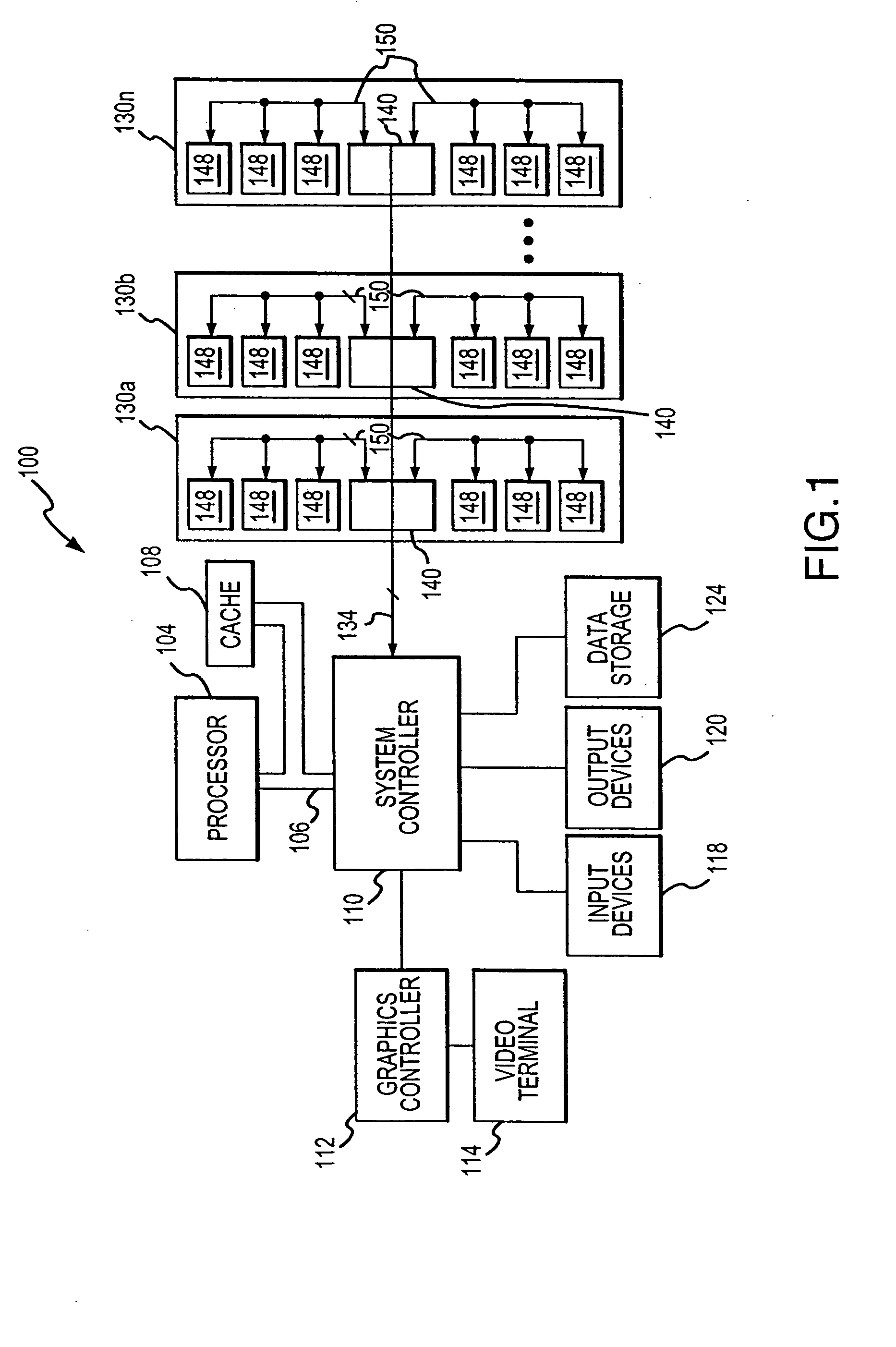
[0011] A computer system 100 according to one example of the invention is shown in FIG. 1. The computer system 100 includes a processor 104 for performing various computing functions, such as executing specific software to perform specific calculations or tasks. The processor 104 includes a processor bus 106 that normally includes an address bus, a control bus, and a data bus. The processor bus 106 is typically coupled to cache memory 108, which, as previously mentioned, is usually static random access memory (“SRAM”). Finally, the processor bus 106 is coupled to a system controller 110, which is also sometimes referred to as a “North Bridge” or “memory controller.”

[0012] The system controller 110 serves as a communications path to the processor 104 for a variety of other components. More specifically, the system controller 110 includes a graphics port that is typically coupled to a graphics controller 112, which is, in turn, coupled to a video terminal 114. The system controller 11...


PUM


Abstract

A computer system includes a memory hub controller coupled to a plurality of memory modules. The memory hub controller includes a memory request queue that couples memory requests and corresponding request identifier to the memory modules. Each of the memory modules accesses memory devices based on the memory requests and generates response status signals from the request identifier when the corresponding memory request is serviced. These response status signals are coupled from the memory modules to the memory hub controller along with or separate from any read data. The memory hub controller uses the response status signal to control the coupling of memory requests to the memory modules and thereby control the number of outstanding memory requests in each of the memory modules.

Description

TECHNICAL FIELD [0001] This invention relates to memory systems, and, more particularly, to a memory system having several memory modules each of which includes a memory hub coupled to several memory devices. BACKGROUND OF THE INVENTION [0002] Computer systems use memory devices, such as dynamic random access memory (“DRAM”) devices, to store instructions and data that are accessed by a processor. These memory devices are normally used as system memory in a computer system. In a typical computer system, the processor communicates with the system memory through a processor bus and a memory controller. The processor issues a memory request, which includes a memory command, such as a read command, and an address designating the location from which data or instructions are to be read. The memory controller uses the command and address to generate appropriate command signals as well as row and column addresses, which are applied to the system memory. In response to the commands and addre...

Claims


Application Information

Patent Timeline
IPC IPC(8): G06FG06F13/16G06F12/00G06F12/02G06F12/06G11C5/00
CPCG06F13/1673G06F13/1642G06F12/00G06F12/02
Inventor JEDDELOH, JOSEPH M.LEE, TERRY R.
Owner ROUND ROCK RES LLC
Why Eureka
Try Eureka