Paper cutter

a cutter and paper technology, applied in the field of paper cutters, can solve the problems of difficult operation of removing the slider, and achieve the effect of easy pulling out of the slo

Inactive Publication Date: 2005-03-31
CARL JIMUKI
View PDF3 Cites 6 Cited by
  • Summary
  • Abstract
  • Description
  • Claims
  • Application Information

AI Technical Summary

Benefits of technology

[0028] When a paper cutter with a long slot is used, paper to be cut by nipped between the plate and the base can be large-siz. In a case in which large-sized paper is cut, when the slider is slid in the slot, there are cases in which the slider strikes, with its own force, on the stopper disposed in the vicinity of the end portion of the slot. Even if the slider strikes on the stopper, the stopper is locked so as not to be rotatable with respect to the holding member, whereby the stopper is prevented from rotationally moving in the direction in which the opening portion of the plate is opened, and the slider can be surely prevented from falling off via the opening of the slot to the outside.
[002

Problems solved by technology

Further, when taking out the slider from the slot special attention is required so as not to cut finger

Method used


Image

  • Paper cutter
  • Paper cutter
  • Paper cutter

Examples


first embodiment

[0066] (First Embodiment)

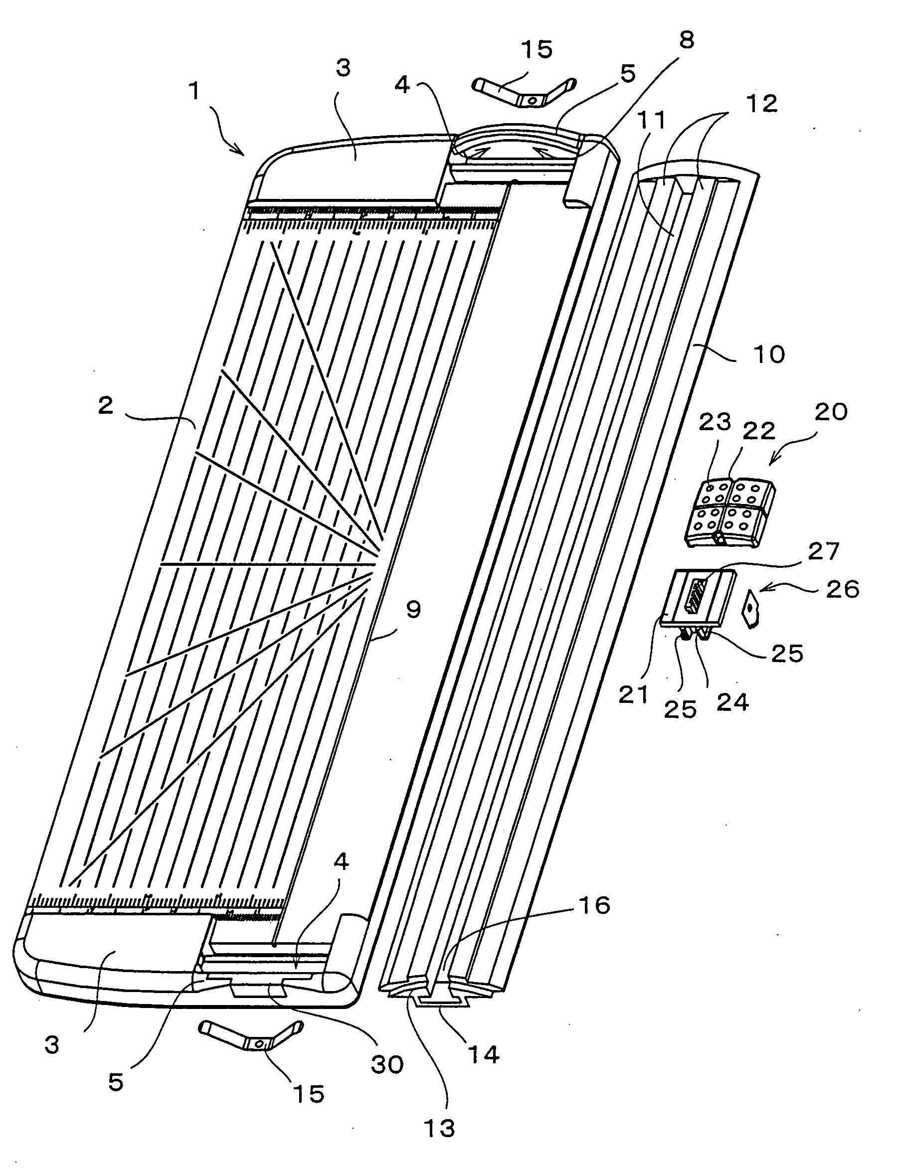
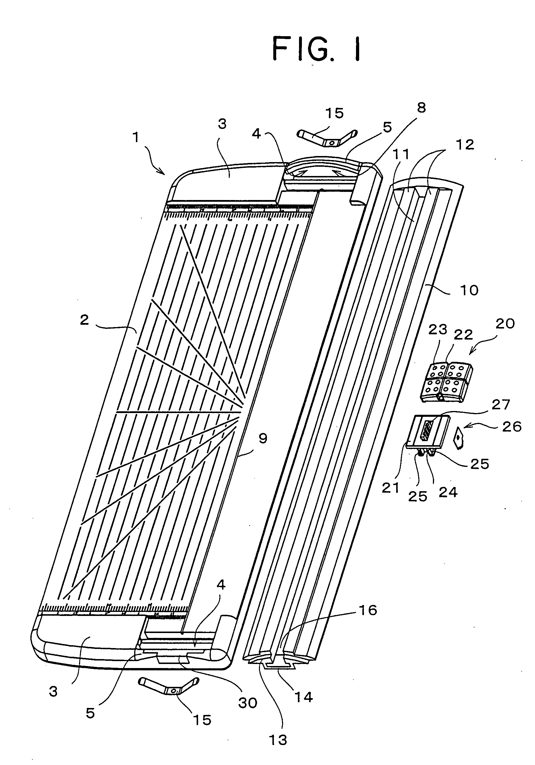
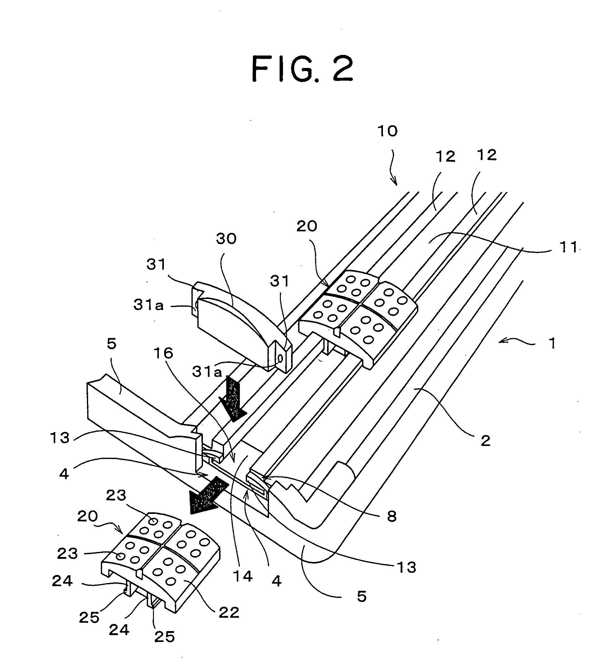
[0067]FIG. 1 is a whole body drawing in which main component members of a paper cutter in a first embodiment according to the invention are disassembled. FIGS. 2 to 5 are partial enlarged views showing a configuration of a stopper which opens and blocks an opening portion at an end portion of a slot and a state of taking-out a slider.

[0068] As shown in FIG. 1, a paper cutter 1 holds a plate 10 to which a paper presser plate is annexed, so as to be able to contact and be separated in the direction of the surface of a base, at end portions of a base 2. Further, springs 15 are interposed between the back surface side of the plate 10 and the base 2, and the plate 10 is urged upward by the springs 15. A slot 11 is formed along the direction of the length of the plate 10 at the center of the plate 10, and one end portion of the slot 11 is opened, and the one end portion is formed as an opening portion 16 at which a slider 20 can be inserted-into and taken-out alo...

second embodiment

[0090] (Second Embodiment)

[0091] FIGS. 6 to 11 show a second embodiment in which the plate 10 is made to be rotatable with respect to the base 2, and the other configurations except for the configuration in which the plate 10 is rotationally moved have the configurations which are the same as in the first embodiment. Therefore, description of the members will be omitted by using the member reference numerals which are the same as the member reference numerals used in the first embodiment.

[0092] Note that, in the first embodiment, an example is shown in which the bridge 14 is formed at least at the end portion, at which the opening portion 16 is provided, of the plate 10. However, because both end portions of the plate 10 in the second embodiment are supported by a pair of arms 6, 6, it is not necessarily needed to form the bridge 14 at the end portion, at which the opening portion 16 is provided, of the plate 10, and in the second embodiment, a case in which the bridge 14 is not fo...

third embodiment

[0100] (Third Embodiment)

[0101] In the first and second embodiments, the examples in which the stoppers 30 are respectively attached to the flange portion 5 and the arm 6 are shown. However, in a third embodiment, an example in which the stopper 30 is detachably attached to the plate 10, or is rotatably attached to the plate 10, is shown.

[0102] As the plate 10 in the third embodiment, any of a configuration in which the plate 10 is made to contact and be separated from the base 2 in the direction of the surface by being guided by the flange portion 5 as in the first embodiment, and a configuration in which the plate 10 is made to be rotationally moved with respect to the base 2 by being attached to the arm 6 as in the second embodiment, can be used. Therefore, an attaching configuration in the vicinity of the attaching portion of the stopper 30 and the plate 10 will be described, and the whole body configuration of the paper cutter and the configurations relating to the plate 10 an...


PUM


Abstract

An end surface of a stopper is formed so as to be thick which is substantially the same surface as an outer circumferential surface of a flange portion, and the stopper is engaged with an engaging groove formed at the flange portion, whereby an engaging portion formed at a locking piece of the stopper is elastically deformed and engages with an engaging portion formed at the flange portion. When the stopper is pulled out in the direction away from the surface of the base resisting with elastic force of the engaging portion, an opening portion of a slot can be opened. The paper cutter of the invention enables to take the slider out of a plate in spite of having a simple configuration, and prevent a falling of the slider from the plate even in conveying it.

Description

BACKGROUND OF THE INVENTION [0001] 1. Field of the Invention [0002] This invention relates to a paper cutter, and in particular, to a paper cutter in which a slider having a cutter slides along a slot of a plate. [0003] 2. Description of the Related Art [0004] Conventionally, a paper cutter for cutting paper placed on a base by sliding a slider having a cuter along a slot of a plate is used. In this kind of paper cutter, when the slider having the cutter is taken out of the slot of the plate, space of the slot is broadened by twisting the plate, or the like, and the slider is taken out of the broadened space. That is, space through which a stopper formed at the back surface side of the slider can be taken out is formed by broadening the slot, and the slider is removed from the slot by taking out the stopper through the broadened space. [0005] Moreover, in order to take the slider out of the slot, it is necessary to broaden the space of the slot and to move the slider to the area of ...

Claims


Application Information

Patent Timeline
IPC IPC(8): B26D1/04B26D1/06
CPCB26D1/045Y10T83/7487
Inventor MORI, MAKOTOSUZUKI, HIDEYUKIKATO, MASAYUKIYAMASHITA, AYANO
Owner CARL JIMUKI
Why Eureka
Try Eureka