
Intake air management apparatus for a vehicle, and motorcycle including same

Inactive Publication Date: 2005-03-31
HONDA MOTOR CO LTD
View PDF3 Cites 22 Cited by
  • Summary
  • Abstract
  • Description
  • Claims
  • Application Information

AI Technical Summary

Benefits of technology

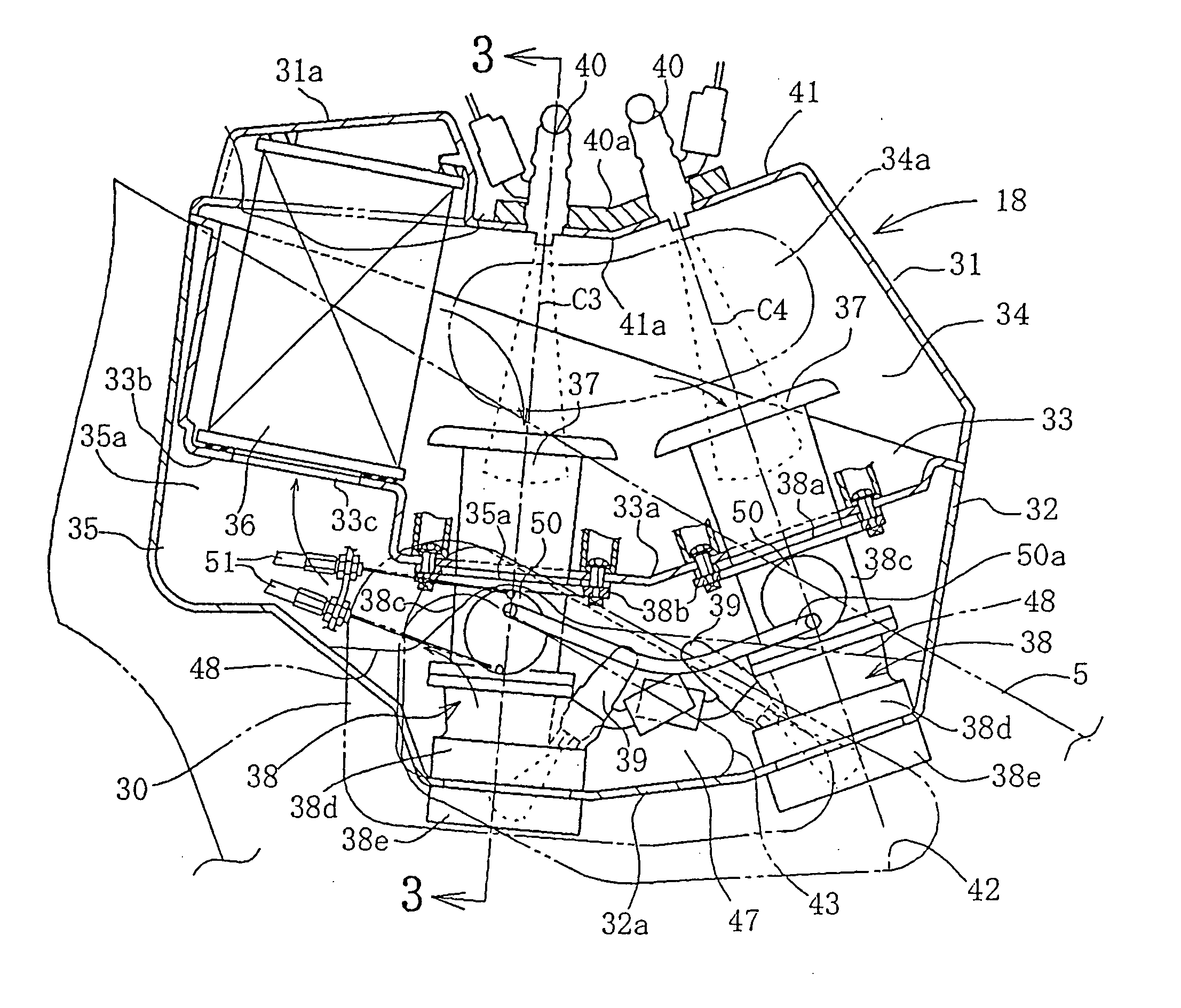
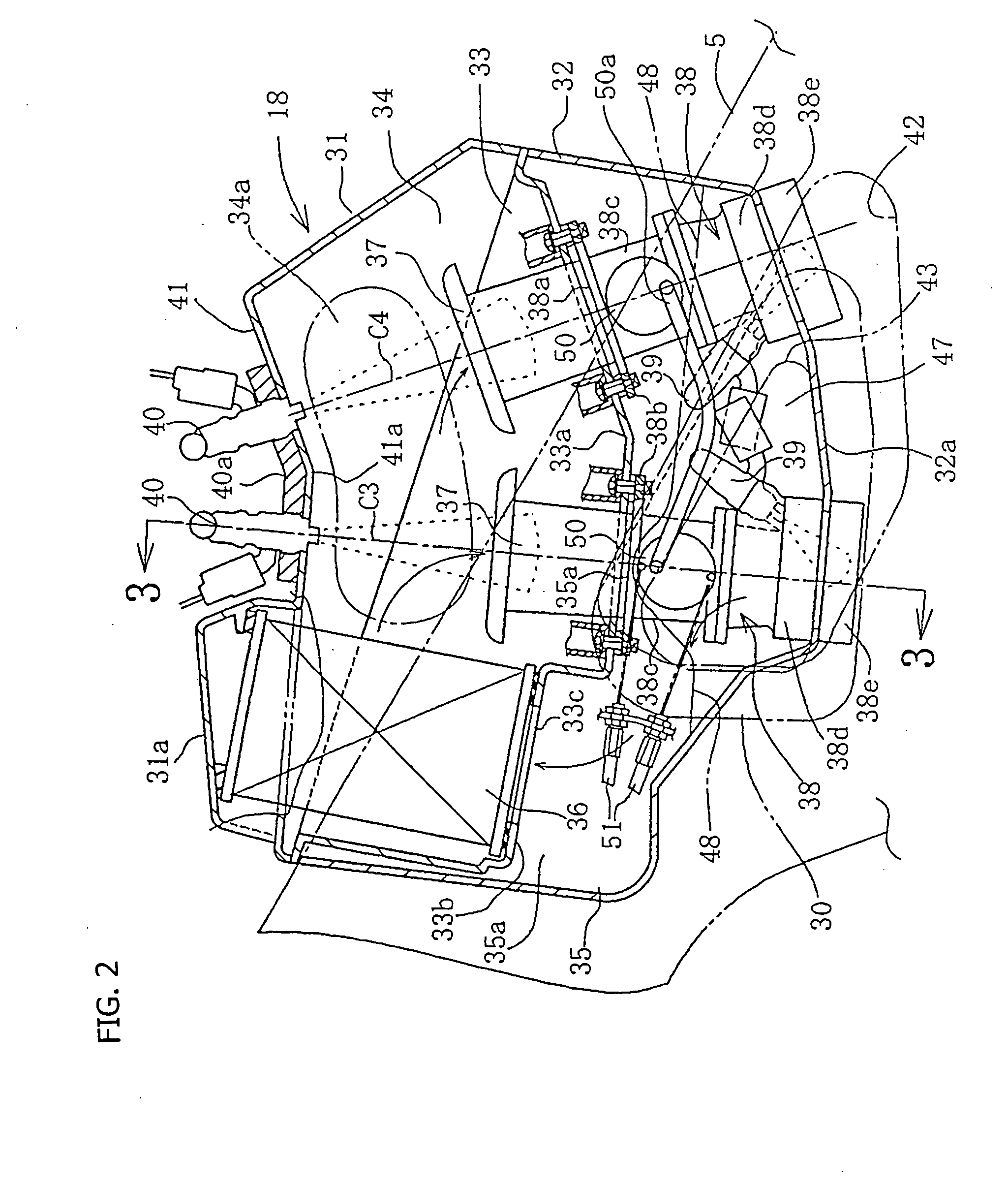
[0025] Therefore, it is unnecessary to mount the air cleaner element between the front and rear intake passages, and the air cleaner element can be disposed comparatively freely in the air cleaner housing spaced away from the plenum.
[0027] According to the second aspect hereof, the injectors are provided at the upper surface of the air cleaner housing at the plenum portion above the intake passages. Therefore, the air cleaner element is not interposed between the injector arrangement positions, which makes it possible to narrow the interval between the injectors, and to make the intake apparatus compact. Particularly, when the front and rear intake passages are relatively inclinedly disposed, so that their axes gradually approach each other toward the upper side, the injector arrangement positions are located on the extensions of the axes, so that the interval can be further reduced.
[0031] According to a fourth aspect of the invention, since the air cleaner element is provided at the front portion of the air cleaner housing, the space for disposing necessary component parts such as auxiliary injectors and the like can be easily secured on the rear portion side in the air cleaner housing.

Problems solved by technology

However, since the positions of the outlets and the layout of the throttle bodies are limited by the bank angle of the front and rear cylinders, there are a large number of limitations as to the air cleaner element and the unfiltered side.
Further, when it is intended to enlarge the volume of the air cleaner upwards so as to secure the capacity of the air cleaner, the upward enlargement is restricted because the fuel tank is enlarged along the upper side of the air cleaner housing.

Method used


Image

  • Intake air management apparatus for a vehicle, and motorcycle including same
  • Intake air management apparatus for a vehicle, and motorcycle including same
  • Intake air management apparatus for a vehicle, and motorcycle including same

Examples


Embodiment Construction

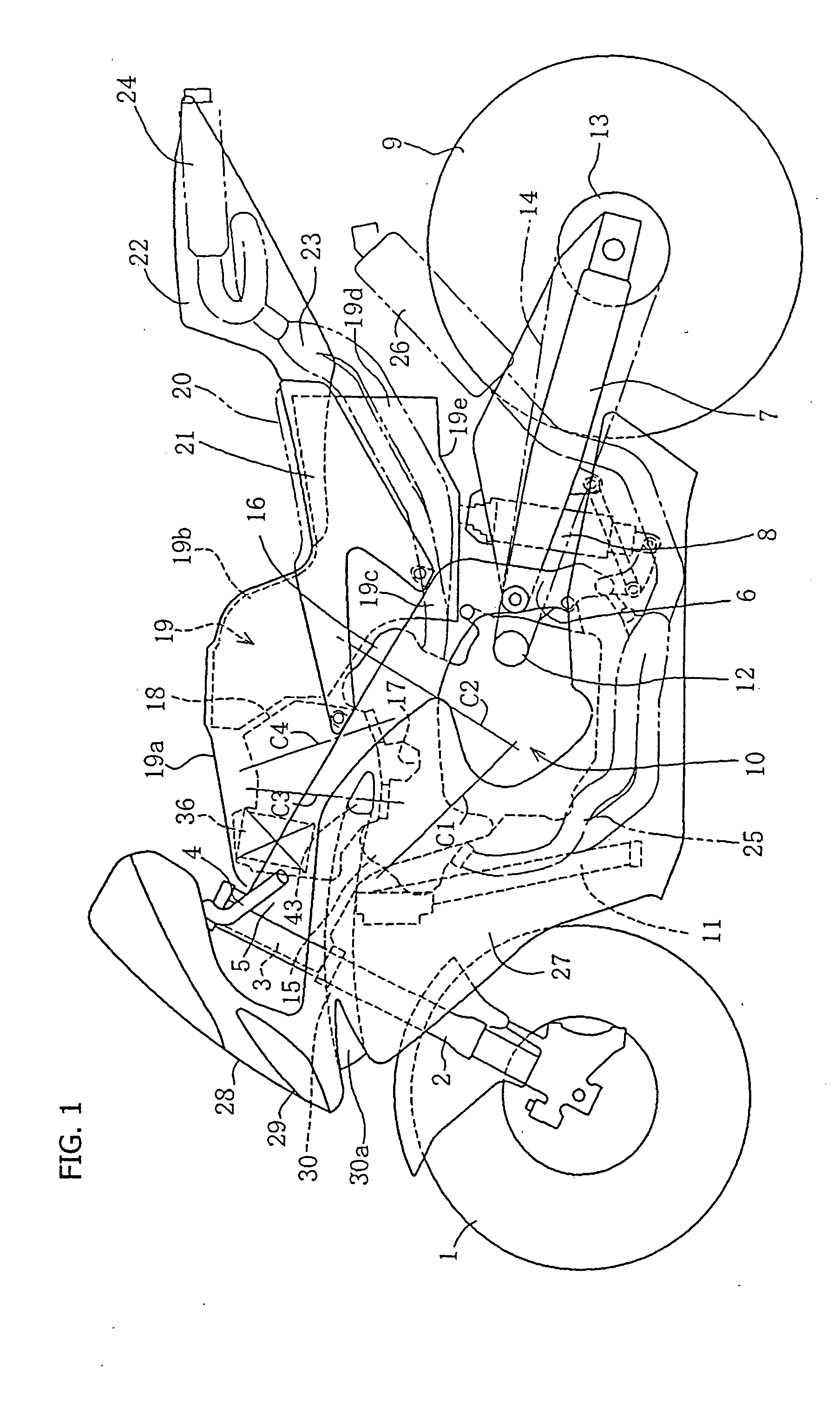
[0037] Now, an embodiment will be described below based on the drawings. FIG. 1 is a side view of a motorcycle to which the present invention has been applied, in which a left-right pair of front forks 2 for supporting a front wheel 1 are provided in the vertical direction. An upper end portion of the front fork 2 is turnably supported by a head pipe 3 through a steering shaft (not shown), and is steerable via a steering handlebar 4, which is operatively connected to the front forks 2.

[0038] A left-right pair of main frame sections 5 branched to the left and right sides extend downwardly rearwards from the head pipe 3. The main frame sections 5 are formed of an appropriate metallic material such as a light alloy, and rear end portions thereof are respectively continuous with upper end portions of a left-right pair of pivot frames 6 extending in the vertical direction. A front end portion of a rear swing arm 7, constituting part of a rear wheel suspension, is swingably connected to ...


PUM


Abstract

An air cleaner housing includes an upper case, a partition wall and a lower case. The inside thereof is partitioned into an upper, filtered side and a lower unfiltered side. Intake funnel pipes, connected to front and rear cylinders, project into the filtered side. An air cleaner element is provided on the front side relative to a hollow plenum above the intake funnel pipes. Inlets in side surfaces of the unfiltered side face toward a V bank of the engine. During use, air enters the bottom of the housing, and is cleaned by the air cleaner element. The clean air flows through the filtered side of the housing, into the intake funnel pipes and toward the cylinders on the lower side. A raised portion is formed on the front upper side of the upper case, and the air cleaner element is disposed inside the raised portion.

Description

CROSS-REFERENCE TO RELATED APPLICATIONS [0001] The present invention claims priority under 35 USC 119 based on Japanese Patent Application No. 2003-342682, filed Sep. 30, 2003, and also based on Japanese Patent Application No. 2003-342683, filed Sep. 30, 2003. The complete disclosure of each of the above-referenced Japanese applications is incorporated by reference herein. BACKGROUND OF THE INVENTION [0002] 1. Technical Field of the Invention [0003] The present invention relates to air cleaners and to intake air routing structure for use in a motorcycle or the like, and particularly to air cleaners which incorporate throttle bodies therein. [0004] 2. Background Art [0005] As one example of a conventional air cleaner for a V-type engine, a structure has been known in which an air cleaner is disposed below a fuel tank and above the V bank of an engine including front and rear cylinders arranged in a V shape, an air cleaner element is provided in a central portion of the air cleaner el...

Claims


Application Information

Patent Timeline
IPC IPC(8): F02B61/02F02B75/22F02D9/10F02M35/04F02M35/10F02M35/116F02M35/16F02M69/04
CPCF02B61/02F02B75/22F02D9/109F02M35/04F02M35/10039F02M69/043F02M35/10072F02M35/10177F02M35/116F02M35/162F02M35/10052
Inventor ISHIKAWA, YUZURUKINOSHITA, YOSHITERU
Owner HONDA MOTOR CO LTD
Learn More