Container refilling system

a refilling system and container technology, applied in the direction of transportation and packaging, liquid handling, packaging goods types, etc., can solve the problems of inconvenient refilling, messy refilling process, frustration of many consumers, etc., to reduce messiness and dripping, reduce the overall refilling experience, and reduce the effect of messiness and dripping

Inactive Publication Date: 2005-03-31
THE PROCTER & GAMBLE COMPANY
View PDF7 Cites 9 Cited by
  • Summary
  • Abstract
  • Description
  • Claims
  • Application Information

AI Technical Summary

Benefits of technology

[0006] The present invention relates to a refilling system for reducing messiness during use includes a container and a refilling container. The container includes a hollow bottle, a pouring spout, and a cap which covers the pouring spout. The pouring spout has an interior surface. The refilling container includes a hollow body a refilling spout and contains a composition therein. The refilling spout has an exterior surface. In the refilling system, the interior surface and the exterior surface are coordinated such that the exterior surface may fit within the interior surface during use.
[0007] It has now been found that by carefully coordinating the size and / or shape of the exterior surface of the refilling spout with the interior surface of the pouring spout, the overall refilling experience can be significantly enhanced. Moreover, messiness and dripping can be minimized or even eliminated, while speed of refilling can be significantly enhanced. As less time is spent in the refilling process, the overall consumer experience is made more satisfying and less stressful. Also significantly less consumer concentration is required when using the refilling system herein.

Problems solved by technology

This refilling experience has now been found to cause frustration with many consumers, as the process is time consuming, especially for viscous compositions which do not pour very quickly.
In addition, the refilling process can be messy as the composition drips or overflows part of the pouring spout and / or container.
Finally, due to the above difficulties, refilling can be inconvenient as the process requires continuous concentration and attention, as the user tries to minimize messiness and keep the product flowing into the container.

Method used


Image

  • Container refilling system
  • Container refilling system
  • Container refilling system

Examples


example 1

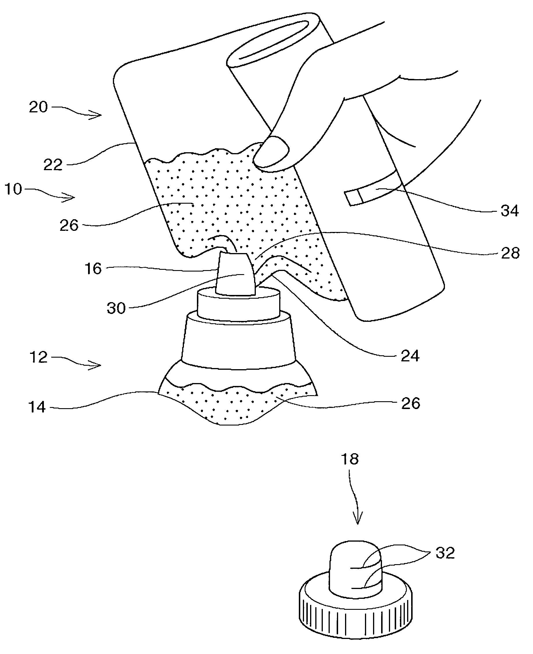
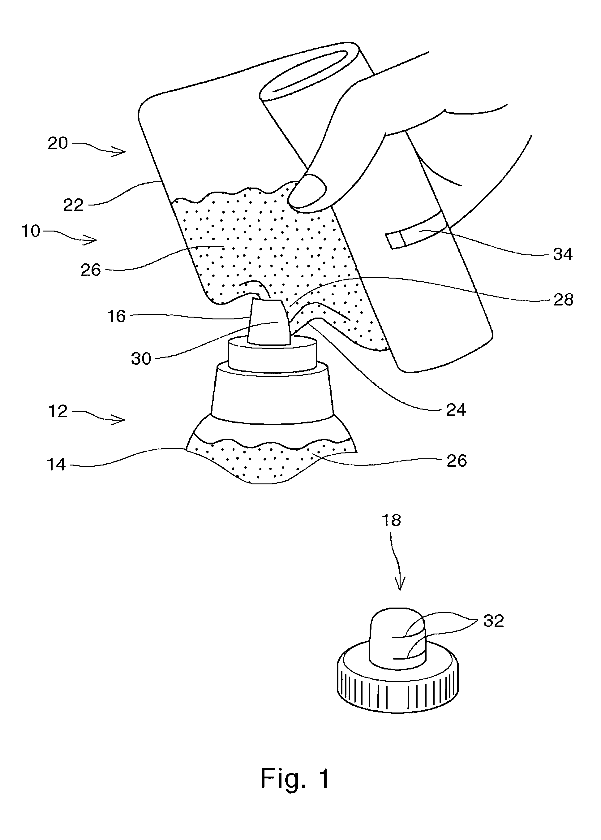
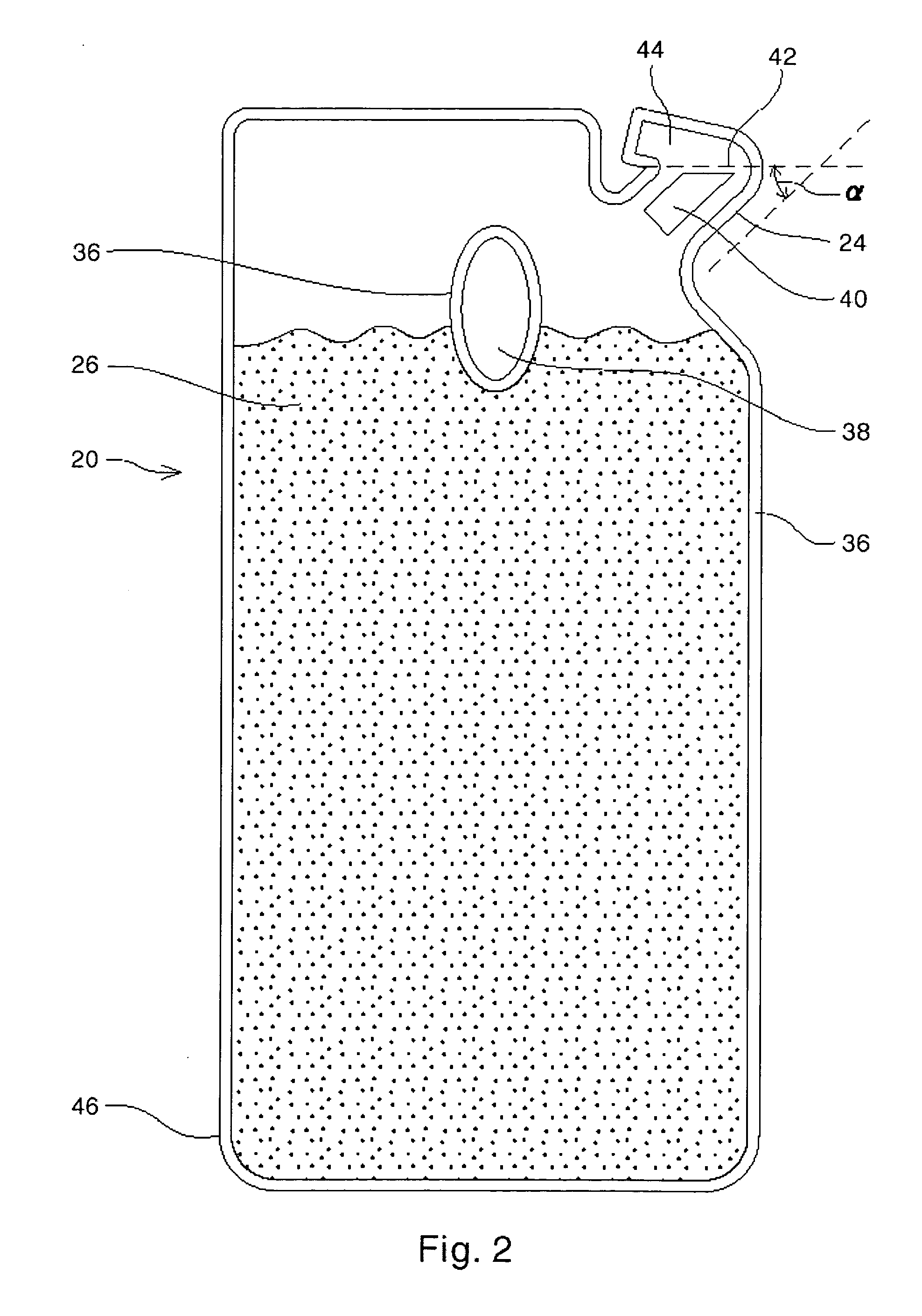
[0028] A refilling system as in FIG. 1 is provided, employing the refilling container of FIG. 2. The container is formed from blow molded polypropylene, and the refilling container is formed of a 155μ thick laminated film containing nylon (25μ) / linear low density polyethylene (130μ). A semi-rigid polyethylene tube is present in the refilling spout. The refilling container contains a clear fabric softening composition.

[0029] The refilling spout has an exterior surface which is generally an oval having a minimum diameter of about 9 mm and a maximum diameter of about 12 mm. The interior surface of the pouring spout is also generally an oval having a minimum diameter of about 12 mm, and a maximum diameter of about 18 mm. Thus, the refilling spout and even the seal edges of the refilling spout fit easily into the pouring spout during use of the refilling system to pour the composition into the container, and the hollow bottle.

[0030] An instruction set is provided on the back of the ref...


PUM

PropertyMeasurementUnit
diameteraaaaaaaaaa
diameteraaaaaaaaaa
diameteraaaaaaaaaa

Abstract

A refilling system for reducing messiness during use includes a container and a refilling container. The container includes a hollow bottle, a pouring spout, and a cap which covers the pouring spout. The pouring spout has an interior surface. The refilling container includes a hollow body a refilling spout and contains a composition therein. The refilling spout has an exterior surface. In the refilling system, the interior surface and the exterior surface are coordinated such that the exterior surface may fit within the interior surface during use.

Description

CROSS REFERENCES TO RELATED APPLICATIONS [0001] This application claims priority to U.S. Provisional Application No. 60 / 487,366, filed Jul. 15, 2003, the disclosure of which is incorporated by reference.FIELD OF THE INVENTION [0002] The present invention relates to containers and refill packages for compositions. More specifically, the present invention relates to containers and refill packages for liquid and granular compositions. BACKGROUND OF THE INVENTION [0003] Containers for holding and dispensing granular and / or liquid compositions, such as laundry detergents fabric softeners, etc., are well known in the art. Containers for granular compositions are often paperboard boxes, but can also be bottle-type containers such as are typically used for liquid compositions. These bottle-type containers typically contain a hollow bottle, a pouring spout, and a cap to prevent spillage. These containers, or parts thereof are usually formed from plastics, polymers, resins, paper, and / or lami...

Claims


Application Information

Patent Timeline
Patent Type & Authority Applications(United States)
IPC IPC(8): B65B1/04B65D75/58
CPCB65D75/5866B65D75/5822B65D47/06B65D75/58
Inventor FURUKAWA, SHIZUKAMIMURA, NOBUOMURAKAMI, RIETOMISHIMA, RYOICHILIN, MICHAEL MING-JAE
Owner THE PROCTER & GAMBLE COMPANY
Why Eureka
Try Eureka