Method and apparatus for slitting steel slabs

a technology of slitting slabs and methods, applied in the direction of soldering apparatus, manufacturing tools,auxillary welding devices, etc., can solve the problems of not being able to provide a high volume, high quality manufacturing line operation for slitting slabs

Active Publication Date: 2005-03-31
EDWARD C LEVY
View PDF34 Cites 25 Cited by
  • Summary
  • Abstract
  • Description
  • Claims
  • Application Information

AI Technical Summary

Problems solved by technology

Whereas these and other slab cutting procedures are generally satisfactory, they are not amenable to the provision of a high volume, high quality manufacturing line operation for slitting slabs.

Method used


Image

  • Method and apparatus for slitting steel slabs
  • Method and apparatus for slitting steel slabs
  • Method and apparatus for slitting steel slabs

Examples


Embodiment Construction

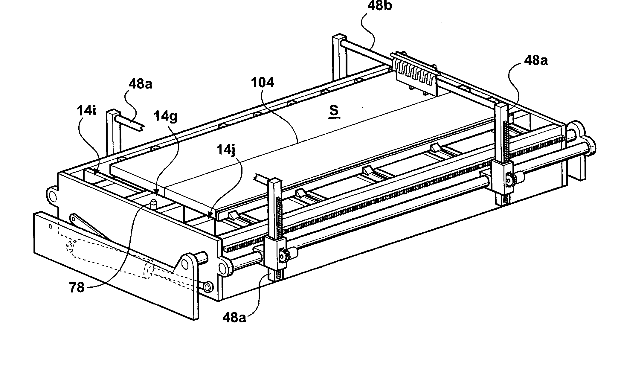
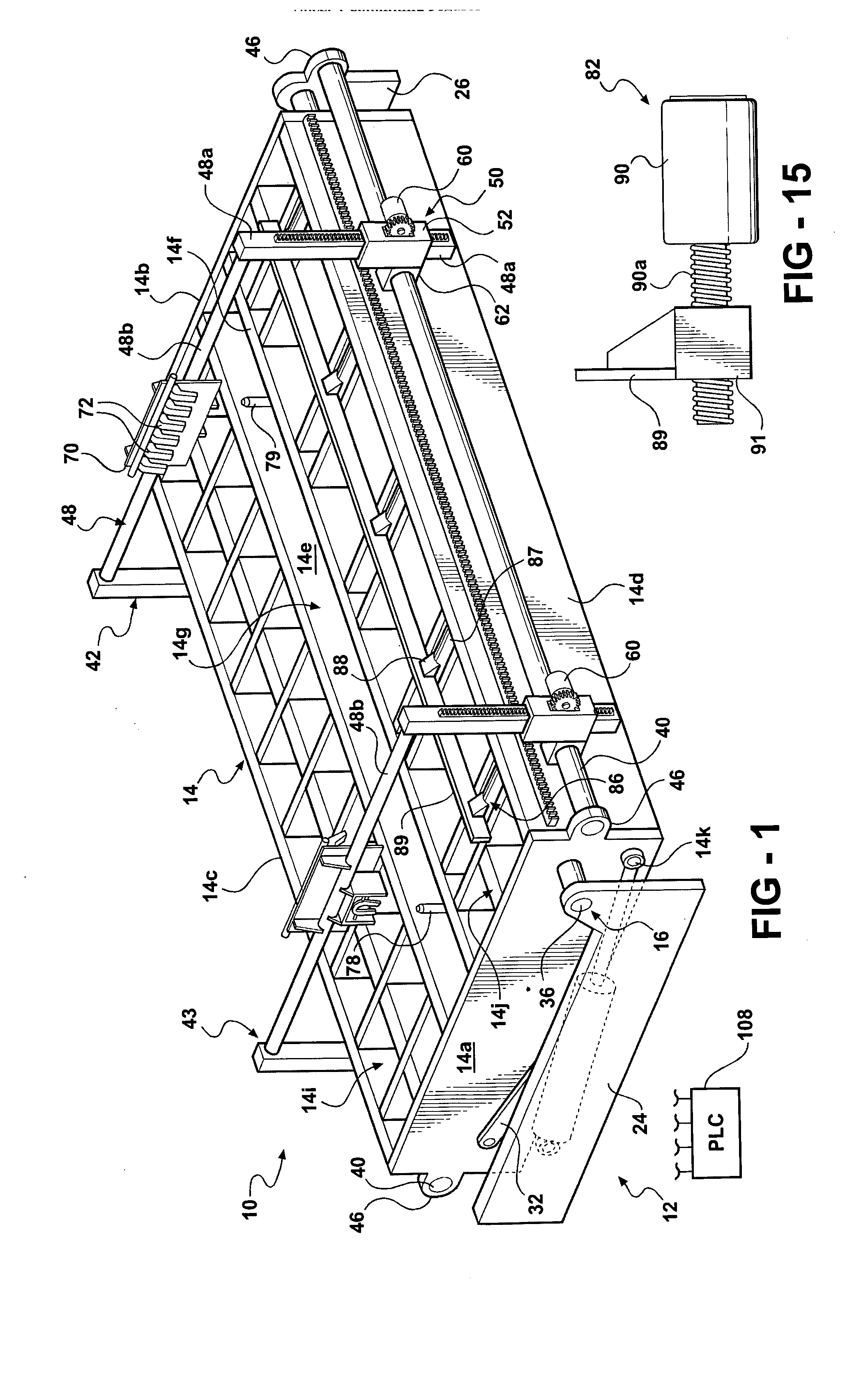
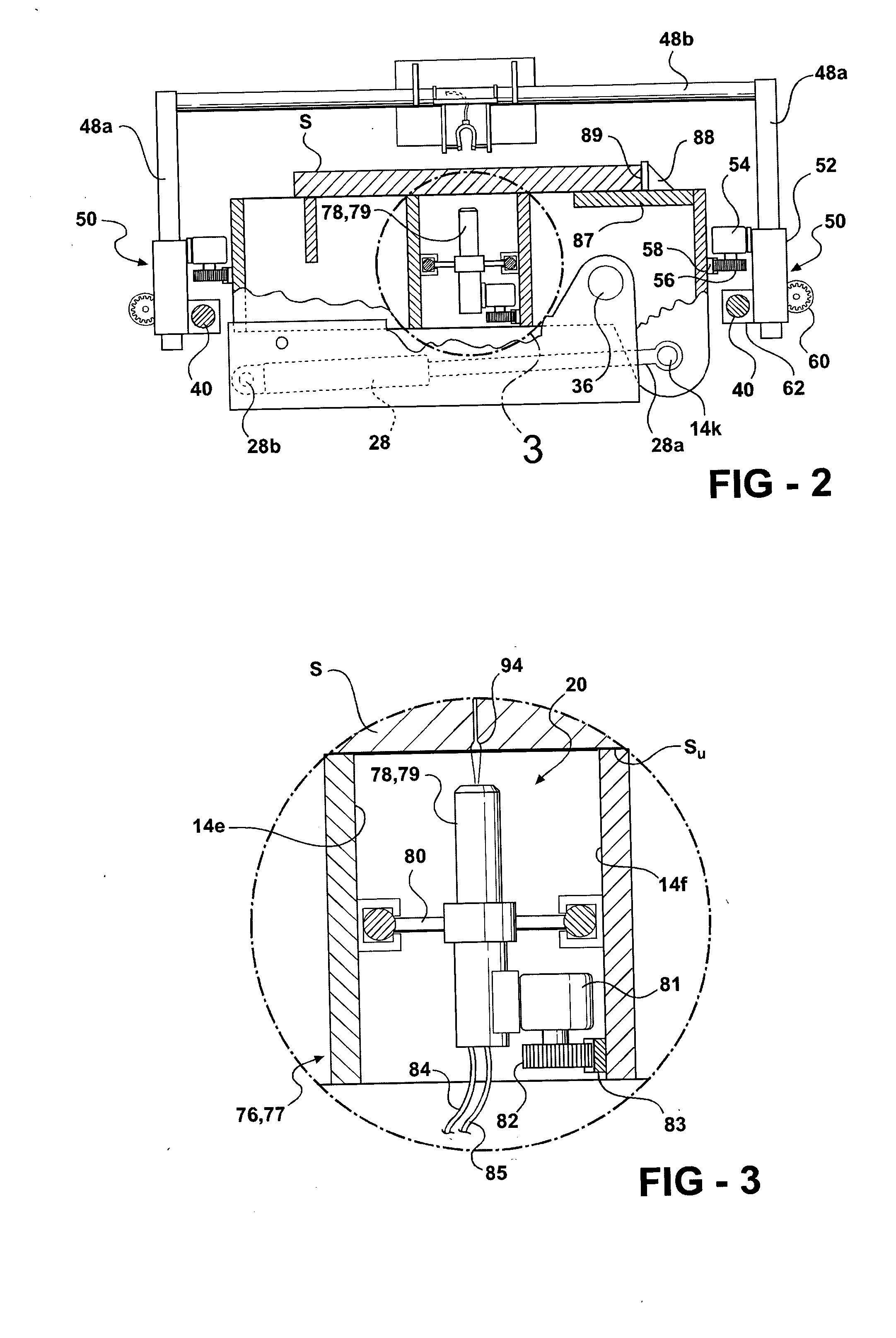
[0040] The invention cutting table 10, broadly considered, includes a base assembly 12, a table assembly 14, a pivot assembly 16, a deburring assembly 18, a torch assembly 20 and a lateral adjustment assembly 22.

[0041] Base assembly 12 is shown schematically and includes spaced base members 24 and 26 adapted to be fixedly secured to a support surface or floor.

[0042] Table assembly 14 includes end plates 14a and 14b, side rails 14c and 14d, central longitudinal beams 14e and 14f defining a slitting slot 14g therebetween, and cross members 14h coacting with members 14c, 14d, 14e and 14f to form a lattice work configuration on an upper loading face 14h of the table. Loading face 14h will be seen to be constituted by a pair of slab loading subfaces 14i and 14j separated by slot 14g.

[0043] Pivot assembly 16 includes a pair of hydraulic rams 28 positioned proximate each base member 24, 26 between the respective base member and a table end plate 14a, 14b, and a pair of links 30, 32 prox...


PUM

PropertyMeasurementUnit
angleaaaaaaaaaa
angleaaaaaaaaaa
angleaaaaaaaaaa

Abstract

A cutting table assembly for oxy cutting comprising a cutting table having a slab loading face and mounted for pivotal movement between a loading position in which the loading face is generally horizontal and a cutting position in which the face is oblique, and a pair of torches mounted on the table. The loading face is constituted by a pair of loading subfaces separated by a slot and the torches are mounted in the slot below the loading face. The torches are positioned at opposite ends of the slot prior to the initiation of the cutting action and, upon the initiation of the cutting action, move toward each other and cut into opposite ends of the slab. A pair of gantries are mounted on the table and each carries a deburring device positioned in overlying opposition to a respective torch. Each gantry further includes a plurality of spaced downwardly directed nozzles which are supplied with compressed air to generate an air curtain.

Description

RELATED APPLICATIONS [0001] This application claims the priority of U.S. Provisional Patent Application No. 60 / 507,352, filed on Sep. 30, 2003.BACKGROUND OF THE INVENTION [0002] This invention relates to oxygen cutting apparatus ad procedures and more specifically to apparatus and procedures for slitting a steel slab utilizing an oxy torch. [0003] Various procedures are known for slitting steel slabs. For example, it is known to place a slab edgewise on a series of feed rollers that carry the slab forward past an oxy cutting torch between pairs of loose mounted vertical rollers. It is also known to slit or cut a slab while lying horizontally or on edge and suspended by means of electro magnets located below the feed rollers. [0004] Whereas these and other slab cutting procedures are generally satisfactory, they are not amenable to the provision of a high volume, high quality manufacturing line operation for slitting slabs. SUMMARY OF THE INVENTION [0005] This invention provides both...

Claims


Application Information

Patent Timeline
Patent Type & Authority Applications(United States)
IPC IPC(8): B23K7/10B23K37/04
CPCB23K37/0461B23K7/10
Inventor ALEXIN, BARRY J.
Owner EDWARD C LEVY
Why Eureka
Try Eureka