Vehicle track chain and link therefor

Inactive Publication Date: 2005-03-31
MACKAY CONSOL INDS
View PDF8 Cites 5 Cited by
  • Summary
  • Abstract
  • Description
  • Claims
  • Application Information

AI Technical Summary

Benefits of technology

[0035] Preferably, each connector has spaced apart end regions with holes for receiving respective link pins there through to connect the connector to the pins. In one preferred

Problems solved by technology

Specifically, the connectors are prone to disengage from their pins thereby causing the chain to break.
That disengagement has occurred because of the ineffectiveness of the connection between the connectors and pins.
In particular, the clamping forces provided by the screws between the connectors and pins have been insufficient to maintain the interconnection under influence of the substantial lead forces applied to the links during chain travel.
Depending on the speed at which the vehicle is travelling when chain breakage occurs, the resulting differential driving forces then applied to the traction chains can force the vehicle to overturn, leading to potentially dangerous consequences.
In particular, because the connectors are located at the ends of the pins, those forces can result in excessive deflections of the pins, leading t

Method used


Image

  • Vehicle track chain and link therefor
  • Vehicle track chain and link therefor
  • Vehicle track chain and link therefor

Examples


Embodiment Construction

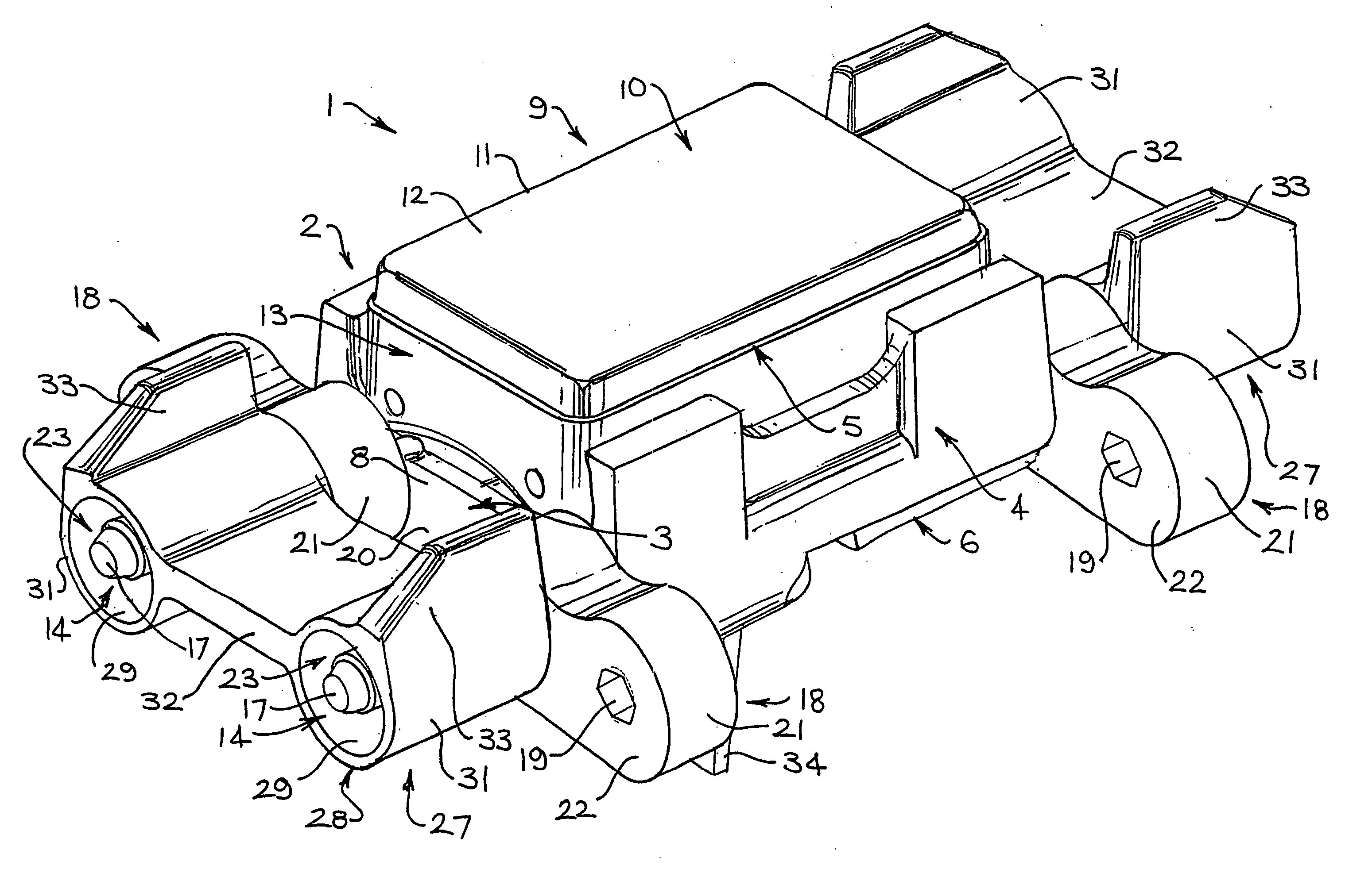
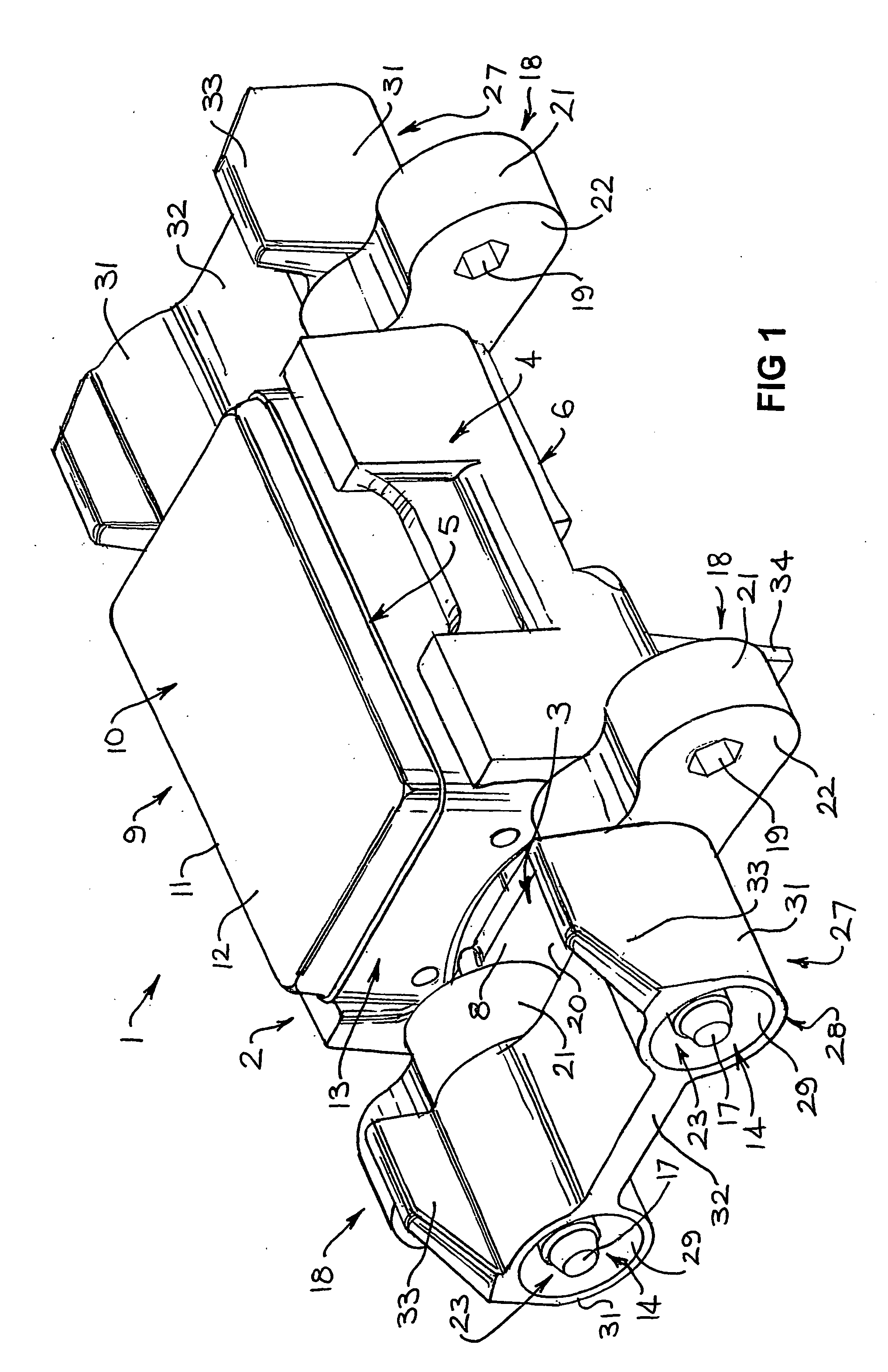
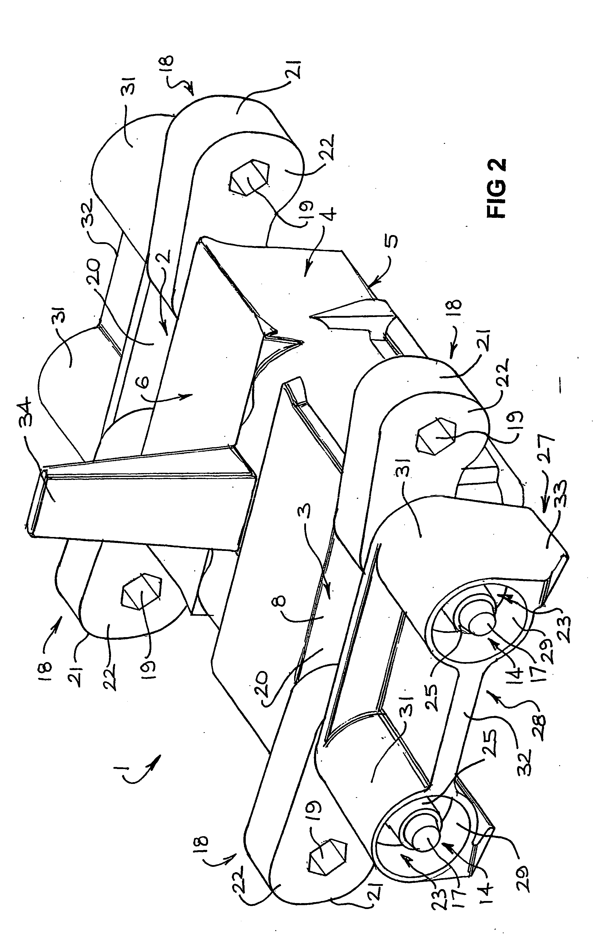
[0053] Referring to FIGS. 1 to 4 of the drawings there is generally shown a chain link 1 for a track chain of a chain traction vehicle (not shown). As will become more apparent hereinafter, with reference to FIG. 7, a plurality of the chain links 1 can be interconnected in seriatim to form an endless track chain 39.

[0054] The chain link 1 includes a link body 2 having a pair of opposite sides 3 and a pair of ends 4 extending between the sides 3. In use, the link 1 is arranged end-to-end with other links 1 in order to form the chain 39, the body sides 3 extending in a longitudinal direction of the chain 39.

[0055] The link body 2 is of a one piece, integral construction in this embodiment. That body 2 may be cast from metal, such as steel.

[0056] The body 2 also has an outer face 5 and an inner face 6 relative to the orientation of the link 1 when in use in a track chain 39. Thus, the outer face 5 is directed outwardly toward ground or another surface over which the chain 39 travels...


PUM


Abstract

A chain link (1) for a track chain of a chain traction vehicle includes a link body (2) having opposite sides (3). Two link pins (14) extending from each side (3) of the link body (2) in spaced relation in a direction of intended travel of the track chain. Connectors (18) are connected to and extending from at least one of the link pins (14). Each connector (18) is also connectable to a juxtaposed pin of an adjacent link (1) so as to interconnect the links (1) into a chain formation. An opening (20) is located outwardly of each side (3) of the link body (2) and between the pins (14) for receiving teeth of sprocket wheels on which the chain is mounted for driving travel of the chain. Fasteners (23) connect with the pins (14) in order to secure the connectors (18) to the pins (14) and interconnect adjacent links into the chain formation. An endless track chain formed of links (1), and connectors (18) for the links (1) are also disclosed.

Description

RELATED APPLICATION [0001] This application is a continuation of International Application Serial No. PCT / AU03 / 00597 filed 19 May 2003, published under PCT Article 21(2) in English, and claiming priority from Australian patent application PS 2380 filed 17 May 2002, and applicant claims the benefit of Australian patent application PS 2380 filed 17 May 2002.BACKGROUND OF THE INVENTION [0002] 1. Field of the Invention [0003] This invention relates to a track chain for chain traction vehicles, as well as a link of the chain. The invention is applicable to armoured vehicles having endless chain traction systems intended both for on and off road travel, and it will be convenient to hereinafter disclose the invention in relation to that exemplary application. It should be appreciated, however, that the invention is not limited to that application. [0004] 2. Description of the Prior Art [0005] A track chain for a chain traction vehicle is disclosed in Australian patent 585458. That track ch...

Claims


Application Information

Patent Timeline
IPC IPC(8): B62D55/20B62D55/21B62D55/28
CPCB62D55/202B62D55/28B62D55/21
Inventor JAMES, ROHAN
Owner MACKAY CONSOL INDS
Why Eureka
Try Eureka