Superconducting magnet apparatus

a superconducting magnet and apparatus technology, applied in the direction of superconducting magnets/coils, instruments, magnetic bodies, etc., can solve the problems of increasing the cost, reducing the maximum allowable current, and unable to keep the superconducting condition stable, etc., to improve the uniformity of the magnetic field of the imaging region, increase the magnetic field, and increase the effect of magnetic spa

Active Publication Date: 2005-03-31
HITACHI LTD
View PDF8 Cites 3 Cited by
  • Summary
  • Abstract
  • Description
  • Claims
  • Application Information

AI Technical Summary

Benefits of technology

[0007] Shortly, it is preferable to bring the main coils close each other in the cooling medium chamber to improve the uniformity of the magnetic field of the imaging region. However, the narrow magnetic space gives the feeling of oppression to the patient. Therefore, It is desirable to make the magnetic space large as much as possible. An object of the present invention is to increase the magnetic field in the magnetic field space at a condition of low current density of the superconducting coils.
[0008] According to the present invention, the magnetic field in the magnetic field space at a condition of low current density of the superconducting coils is increased and maximum experience magnetic field and compression stress of the superconducting coils are reduced.

Problems solved by technology

When experience magnetic field become large, maximum allowable current reduces and it is impossible to keep superconductiong condition stable.
As a result, it is obliged to use expensive wiring material, and therefore, the cost-up occurs.
However, the narrow magnetic space gives the feeling of oppression to the patient.

Method used


Image

  • Superconducting magnet apparatus
  • Superconducting magnet apparatus
  • Superconducting magnet apparatus

Examples


Embodiment Construction

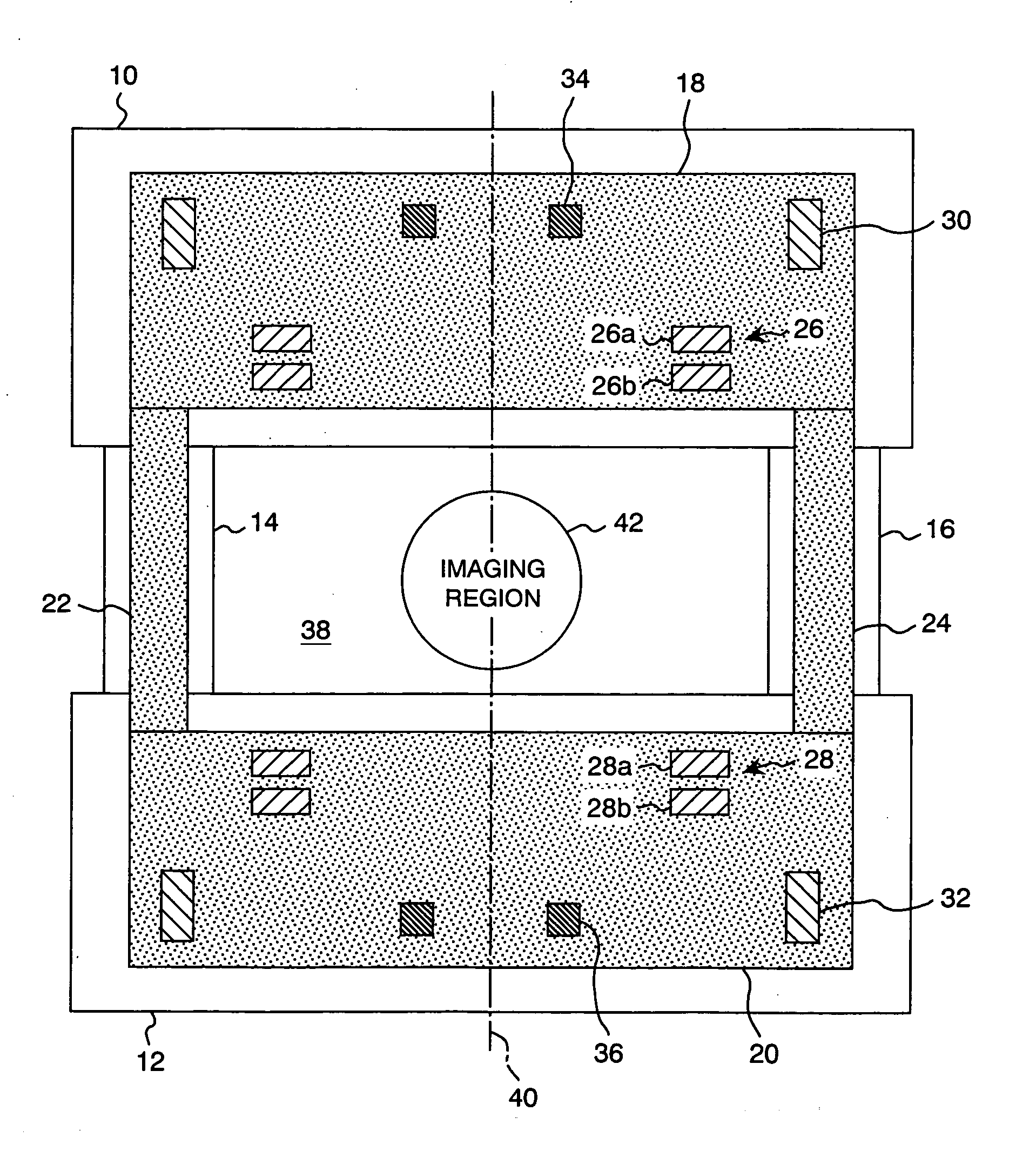
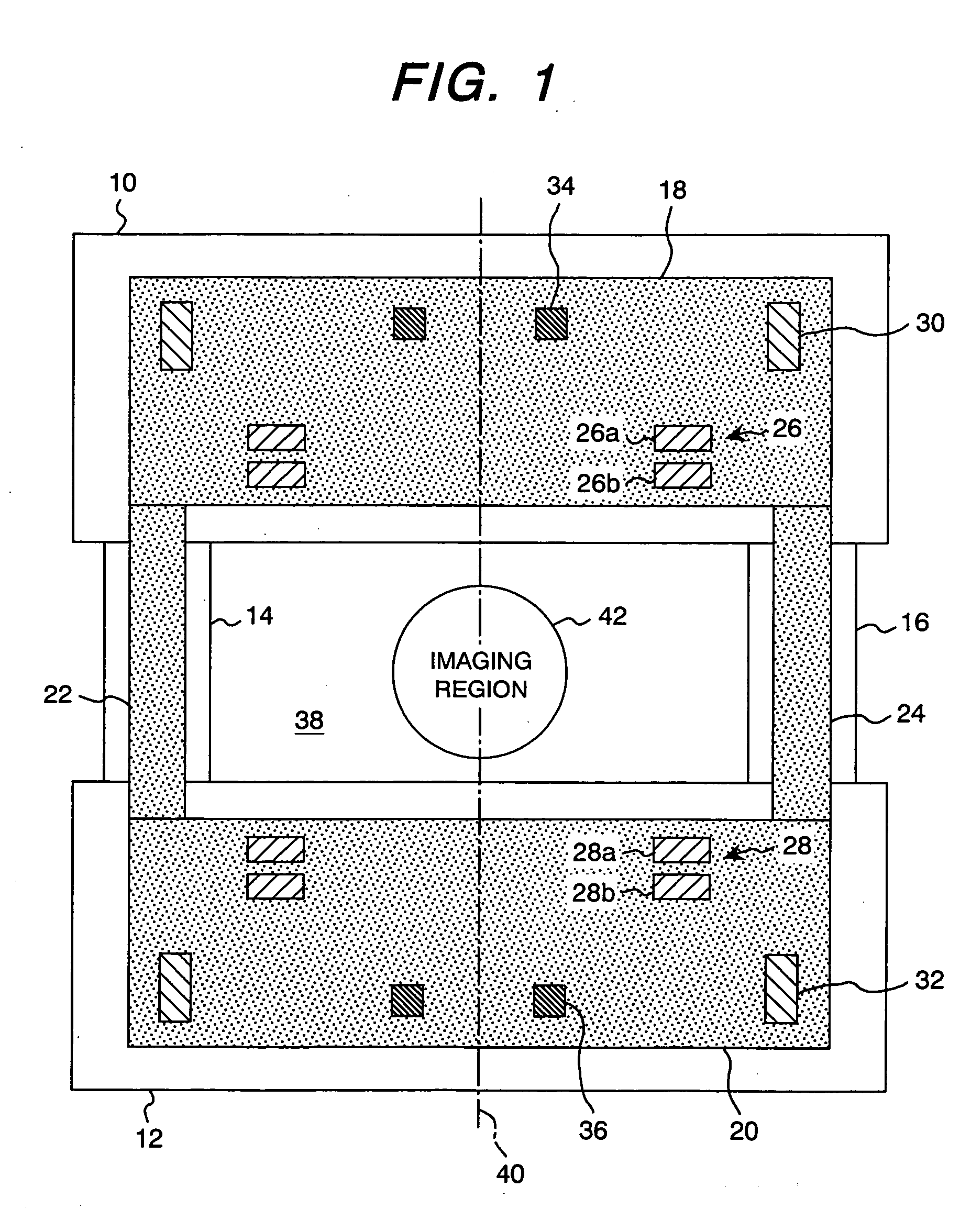
[0014] Hereinafter, an embodiment according to the present invention will be explained with reference to the drawings FIG. 1 is a cross sectional view of the superconducting magnet apparatus showing an embodiment of the present invention. A superconducting magnet apparatus of vertical magnetic field type has a pair of vacuum chambers 10 and 12 and is used as a magnetic field generation source for the magnetic resonance imaging apparatus.

[0015] The vacuum chambers are formed cylindrically and positioned separately at upper and lower portions. The upper vacuum chamber 10 and lower vacuum chamber 12 are connected each other through supports 14 and 16. A cylindrical cooling medium chambers 18 and 20 are accommodated in the vacuum chamber 10 and 12, and pipes 22 and 24 forming cooling paths are inserted into the supports 14 and 16. The cooling medium chambers 18 and 20 opposing each other are accommodated in the vacuum chambers 10 and 12 so as to suppress heat convection.

[0016] The mag...


PUM

PropertyMeasurementUnit
superconductingaaaaaaaaaa
currentaaaaaaaaaa
nuclear magnetic resonanceaaaaaaaaaa

Abstract

Main coils, counteracting coils and correction coils, each forming superconducting coil, are enclosed in two cooling medium chamber facing to each other and an imaging region is formed between the two cooling medium chamber positioned in each vacuum chamber, the main coils being divided into two pieces to reduce the current density and the maximum experience magnetic filed and compression stress.

Description

CLAIM OF PRIORITY [0001] The present application claims priority from Japanese application serial NO. 2003-340210, filed on Sep. 30, 2003, the content of which is hereby incorporated by reference into this application. BACKGROUND OF THE INVENTION [0002] The present invention relates to a superconducting magnet apparatus suitable for a magnetic filed generation source of a magnetic resonance imaging apparatus. [0003] A superconducting magnet apparatus used as a magnetic field generation source of a magnetic resonance imaging, for example, comprises a pair of cooling medium chamber enclosing a plurality of superconducting coils having different diameter and formed annularly, a pair of vacuum chamber enclosing each cooling medium chamber, and a connecting bar connecting each of the vacuum chambers so as to form a magnetic field space (measuring space) between the pair of vacuum chamber. Such apparatus is disclosed in Japanese Laid-open Patent Publication Hei-9-153408 and U.S. Pat. No. ...

Claims


Application Information

Patent Timeline
Patent Type & Authority Applications(United States)
IPC IPC(8): A61B5/055G01R33/3815G01R33/38G01R33/3875G01R33/421H01F6/00
CPCG01R33/3815G01R33/3806
Inventor ABE, MITSUSHINAKAYAMA, TAKESHITAKAHASHI, MASANORI
Owner HITACHI LTD
Why Eureka
Try Eureka